80S-2080F480F5.pdf - 第343页
SIPLACE 80S-20/F4/F5 User M anual 5 Vision Func tions 05/99 Issue from Software Vers ion SR.405.xx 5.6 Test Comp onent Line en gineer 5 - 111 Setting the contrast sensitivity to suppress defecti ve structures Selec t the…

5 Vision Functions SIPLACE 80S-20/F4/F5 User Manual
5.6 Test Component 05/99 Issue from Software Version SR.405.xx
5 - 110 Line engineer
Buttons
– Accept
Click on the
Accept
button to save the settings. The option box will then close.
– Cancel
With
Cancel
you can discard the settings. The option box will then close.
– Help
With the
Help
button you can access explanatory material regarding the on-screen presentation.
– Number
input field
You can choose the number of sections
by entering the numerical value directly into the display field, or
by moving the scroll field in the scroll bar to the right or left using the mouse. In this way you can run
back and forth through the values range (1 - 5), or
by clicking on the lefthand or right-hand arrow on the scroll bar. In this way you can increase or
decrease the number of selections.
Programming the transformation table
– Specifying the output values
Position the mouse pointer over the ends of the transformation lines of each section. The ends are marked
with small horizontal lines. A vertical double arrow will then appear on the screen. Click on the lefthand
mouse key and move the arrow upwards or downwards. This will move the selected end of the transforma-
tion line and the numerical value will be displayed at
OUT Begin
or
OUT End
.
– Selecting the section limits
The graphical representation in Fig. 5.6.30, Page 5 - 109 shows section limits with the ranges 0 - 80, 81 -
180 and so on. You can change these section limits if you wish. However limits 0 and 255 are permanently
allocated and cannot therefore be moved.
Position the mouse pointer on a section limit (but not 0 and 255). A horizontal double arrow will appear on
the screen. Hold down the lefthand mouse pointer and use it to drag the section limit in the direction you
want. The corresponding numerical value will be displayed at
IN:
.
– Once you have programmed your transformation table you can quit the option box by clicking on
Accept
or
Cancel
.
Notes on using the transformation tables to set the contrast sensitivity
– Select up to 3 sections.
– The range of values for the individual sections should be at least 75.
– Program the ranges so that no jumps occur at the range limits.
Set the contrast sensitivity so that the shape of the curve roughly corresponds to one of the three following
examples:
SIPLACE 80S-20/F4/F5 User Manual 5 Vision Functions
05/99 Issue from Software Version SR.405.xx 5.6 Test Component
Line engineer 5 - 111
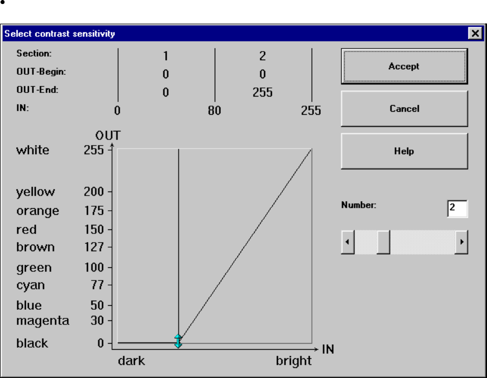
Setting the contrast sensitivity to suppress defective structures
Select the following settings for lighter PCBs or fiducials in order to suppress defective structures.
Fig. 5.6.31 Setting the contrast sensitivity to suppress defective structures
5 Vision Functions SIPLACE 80S-20/F4/F5 User Manual
5.6 Test Component 05/99 Issue from Software Version SR.405.xx
5 - 112 Line engineer
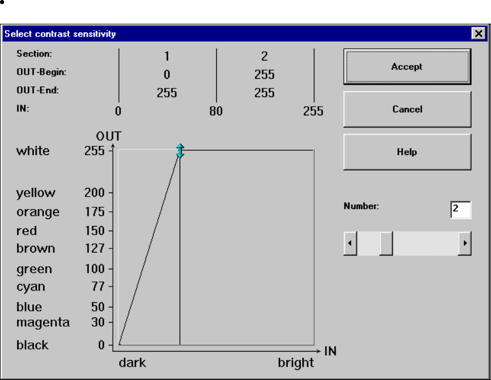
Setting the contrast sensitivity to intensify low-contrast fiducials
Select the following settings for low-contrast fiducials in order to intensify the contrast:
Fig. 5.6.32 Setting the contrast sensitivity to intensify low-contrast fiducials