80S-2080F480F5.pdf - 第489页
SIPLACE 80S-20/F4/F5 User M anual 9 Maintenance 05/99 Issue from Software Vers ion SR.405.xx 9.3 Machine B ase 9 - 23 9.3.3.8 Undocking the component table Fig. 9.3.2 Undocking the mobile component Key to Fig. 9.3.2 (1) …

9 Maintenance SIPLACE 80S-20/F4/F5 User Manual
9.3 Machine Base 05/99 Issue from Software Version SR.405.xx
9 - 22
9.3.3.6 Refitting the Feeder Modules
Remove the cover strips over the compressed air distributor block.
Replace the feeder modules back into the correct track on the components table.
Replace the tapes in the module (see the
Component supply
section of this user’s manual).
NOTE
If you are not certain of the assignment of the rolls to the division, have the location’s set-up displayed in
this way :
Set-up
menu →
Setup location no.
Further information in this connection will be found in the
Components Handling
section of this user’s manual.
Close the safety hoods.
In the
PCB transport
menu select the
Conveyor width
option and set the conveyor back to the width of
the board which is to be processed.
9.3.3.7 Safety instructions for docking and undocking the mobile component table
WARNING
Never reach into the gap between the component tables and the placement system frame while the
machine is running.
Always check that the component table is docked on the placement system before connecting or discon-
necting the component table power cable at the socket on the placement system.
NEVER connect the component table connecting cable to the socket on the placement system and then
operate the component table via the external compressed air control unit.
SIPLACE 80S-20/F4/F5 User Manual 9 Maintenance
05/99 Issue from Software Version SR.405.xx 9.3 Machine Base
9 - 23
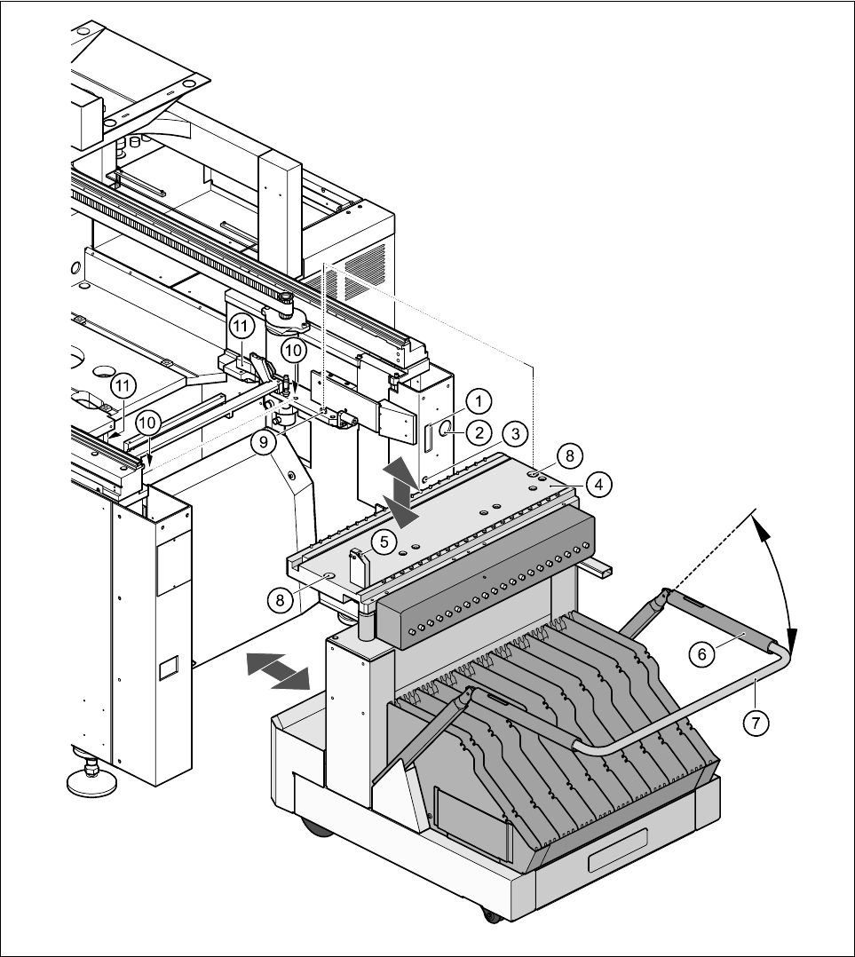
9.3.3.8 Undocking the component table
Fig. 9.3.2 Undocking the mobile component
Key to Fig. 9.3.2
(1) Communication interface connector
(2) Power supply connector for the component table
(3) Compressed air connection
(4) Component table bed
9 Maintenance SIPLACE 80S-20/F4/F5 User Manual
9.3 Machine Base 05/99 Issue from Software Version SR.405.xx
9 - 24
(5) Button for raising and lowering the component table bed
(6) Actuating tube
(7) Fold-down bracket
(8) Holes for the centering pins
(9) Centering pins
(10) Contact surfaces for the slide rails of the component table
(11) Horizontal tensioners
Click on the PAUSE OPERATION icon in the BASIC VIEW menu.
The PCB in progress will be completed. The icons of the SINGLE FUNCTIONS menu will then be acti-
vated.
Click on the desired SINGLE FUNCTIONS GANTRY X icon (gantry 1 or 2).
Click on the GANTRY FUNCTIONS icon.
From this menu, click on the APPROACH SET-UP POSITION button.
The selected placement head will move across the PCB transport to prevent it being damaged when the
component table is changed.
Open protective cover of the selected gantry.
Open the side screens.
Open the horizontal tensioners (item 11)
Pull the two actuating tubes (item 6) towards you at the same time and lift up the bracket (item 7) to lock
the raised component table bed in its top end position.
Hold down the button (item 5) for raising the component table bed (item 4) until the component table bed
reaches its top end position.
Unplug the component table power cable (item 2).
Unplug the component table control cable (item 1).
Disconnect the compressed air supply (item 3).
Remove the component table.
9.3.3.9 Docking the component table
WARNING
Check that the placement head is outside the range of the component table.
CAUTION
When docking the component table, ensure that the table bed is in its top end position and the bracket (item 7)
is folded up.
Cut off the empty tapes for the feeder modules.
Make sure that the contact surface (item 10) for the component table bed is clean.
CAREFULLY push the component table into the placement system.