CM88Maintenace1.pdf - 第164页
Page 1-126 3Y3C-E-MMD01-A12-02 Replacing Batteries 1-8-3 Replacing SCMYEX (SCMWEX) Battery 1) Save the machine data and the machine parameter to the floppy disk. 2) Turn of f the power . 3) Remove two screws at the upper…
Page 1-125
REGULAR
MAINTENANCE
1
C
N
0
1
C
N
2
5
C
N
0
0
C
N
1
3
C
N
2
0
C
N
5
1
C
N
2
7
C
N
5
S
W
1
C
N
4
C
N
1
9
C
N
2
3
C
N
2
4
C
N
5
0
C
N
2
6
C
N
1
4
C
N
2
8
C
N
2
9
C
N
3
0
C
N
3
1
C
N
3
2
C
N
3
3
C
N
3
4
N
R
1
N
R
2
C
N
1
8
C
N
8
C
N
7
C
N
T
E
S
T
3
C
N
T
E
S
T
4
CNTEST 1
CNTEST 2
CN2
CN1
CN21
CN22CN17
CN11
CN12
CN9
CN10
CN15
CN1
CN2
CN3
OPT1OPT2OPT3OPT4OPT5
OPT6OPT7
CN1
CN2
CN3
CN1
CN2
CN3
CN4
CN4
CN2
CN1
CN3
CN5
CN
10
CN
9
CN
7
CN
6
CN1CN2
CN3
CN4
CN5
CN6
CN2
CN3
CN4
CN5
CN
8
N
C
G
N
D
1
1
2
V
G
N
D
2
G
N
D
1
+
5
V
+
2
4
V
-
1
2
V
+
1
2
V
+
5
V
G
N
D
3
+
2
4
V
-
1
2
V
+
1
2
V
GND
2
GND
1
+
5
V
C
N
C
G
N
D
3
+
2
4
V
-
1
2
V
G
N
D
2
+
1
2
V
G
N
D
1
+
5
V
N
C
L
N
F
G
E
C
5
5
C
A
N
F
M
0
C
K
C
M
M
7
C
A
M
C
M
A
E
R
P
R
M
7
E
Q
E
L
L
Z
E
A
S
C
M
W
E
E
P
U
0
2
E
1
G
N
D
+
5
V
N
C
G
N
D
1
G
N
D
+
5
V
Replacing Batteries
3Y3C-E-MMD01-A12-02
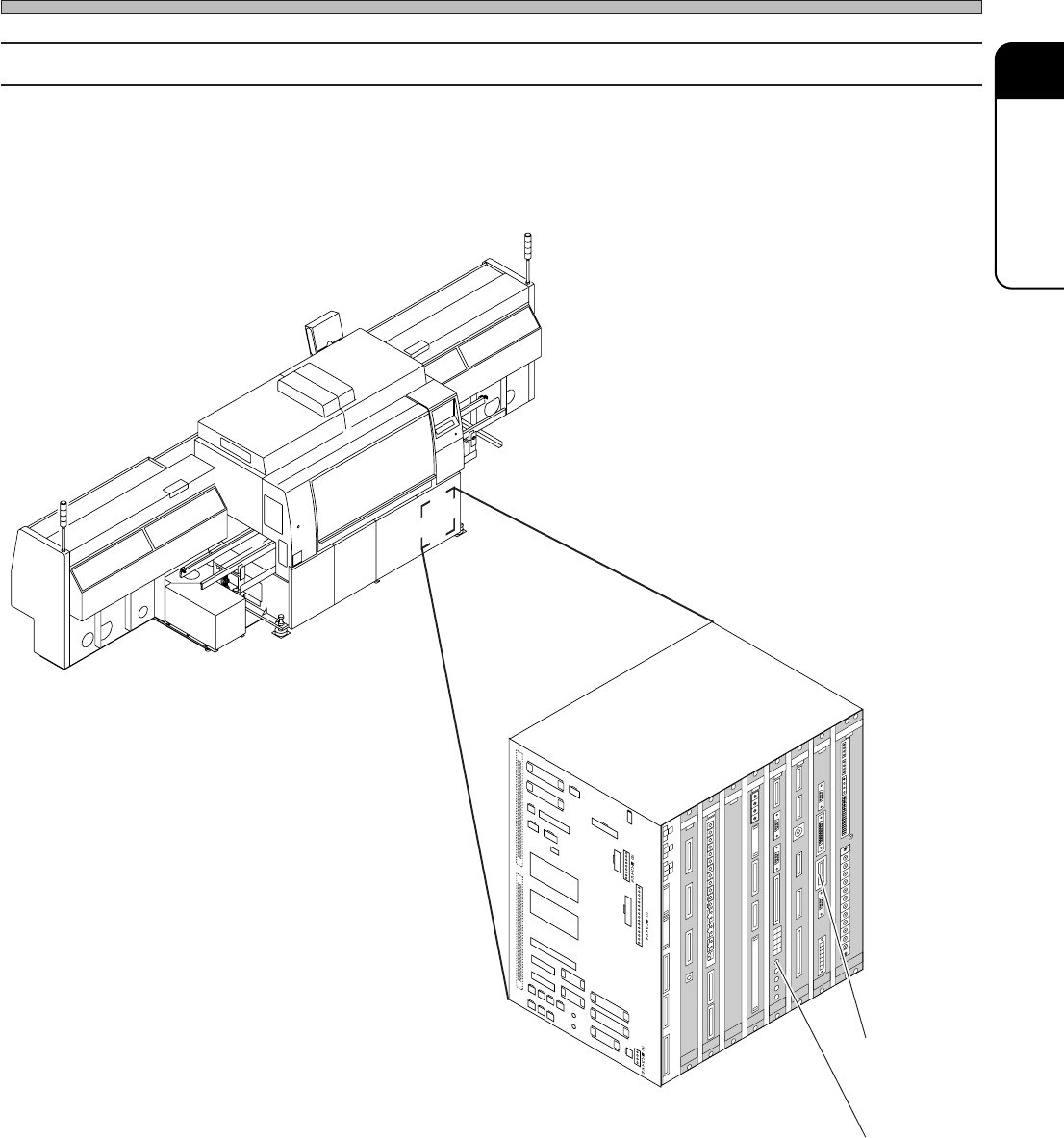
1-8-2 Battery Locations
4G3C-AA01
3Y3C-109E
[CPU-BOX]
1. SCMYEX
(SCMWEX)
2. PRM9EX
∗ This is described with the illustration of CM88S-M.
Page 1-126
3Y3C-E-MMD01-A12-02
Replacing Batteries
1-8-3 Replacing SCMYEX (SCMWEX) Battery
1) Save the machine data and the machine parameter to the floppy disk.
2) Turn off the power.
3) Remove two screws at the upper and lower positions, and remove the SCMYEX (SCMWEX)
board.
4) Remove the battery set to the board.
5) Set the new battery.
6) Set the SCMYEX (SCMWEX) board and turn on the power.
7) Load the machine data and the machine parameter.
1-8-4 Replacing PRM9EX Battery
1) Save the machine data and the machine parameter to the floppy disk.
2) Turn off the power.
3) Remove two screws at the upper and lower positions, and the PRM9EX board.
4) Remove the battery set to the board.
5) Set the new battery.
6) Set the PRM9EX board and turn on the power.
7) Load the machine data and the machine parameter.
8) Install the recognition software.
Page 1-127
REGULAR
MAINTENANCE
1
1-9 Replacing the Consumable Parts
3Y3C-E-MMD01-A12-00
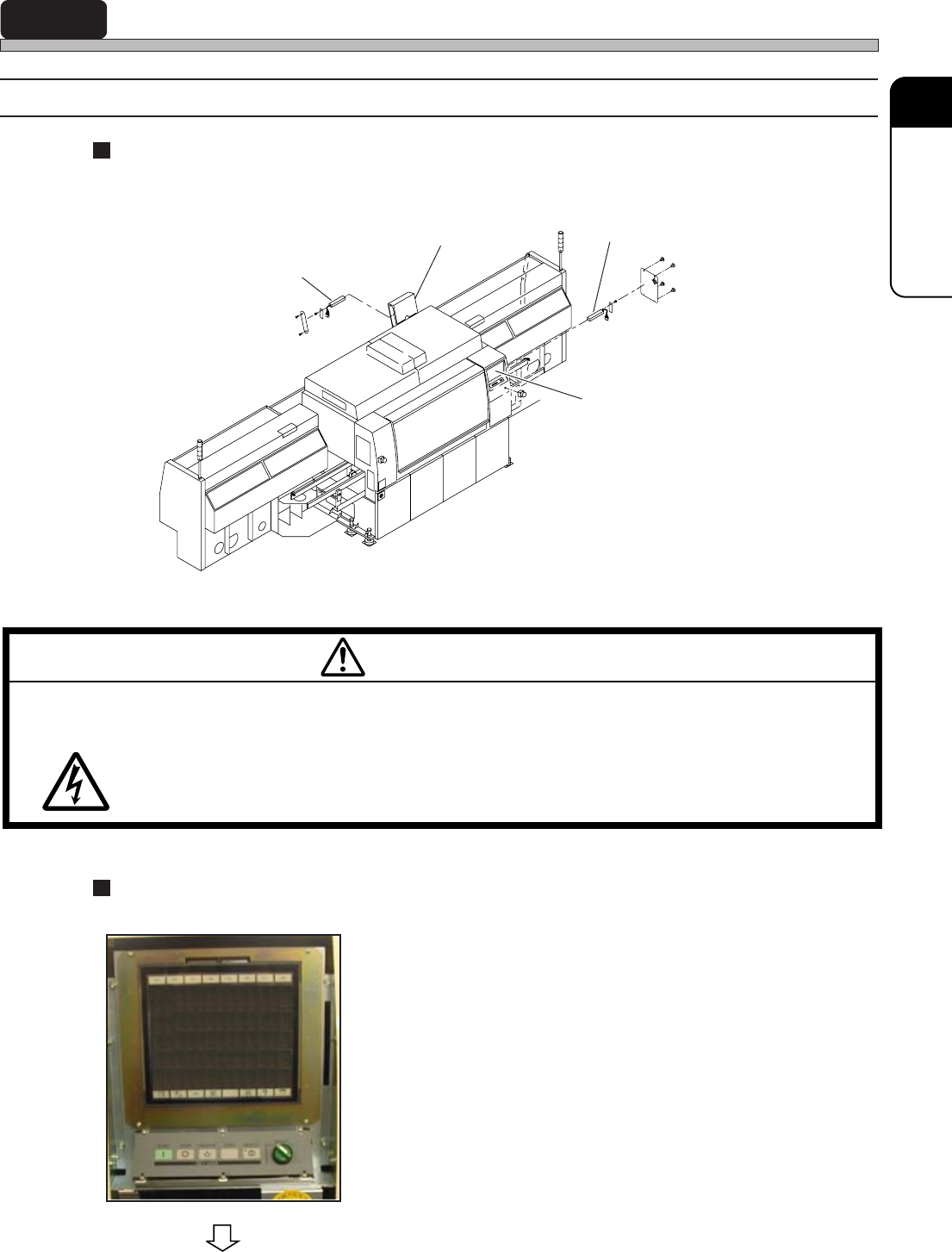
1-9-1 Replacing Color Touch Panel Back Light
Back Light Built-in Color Touch Panel Position (Front side, Rear side)
The color touch panel of this machine has a back light built-in.
Back Light Replacement Procedure
1. Turn OFF the power supply of the
machine.
2. Remove the cover located at the side
of the color touch panel.
M59EB
CUT OFF THE POWER SUPPLY BEFORE CARRYING OUT ANY WORK FOR
THE MACHINE.
You will have a serious electric shock.
WARNING
To the next page
493C-025P
Back light
Color touch panel
Back light
Color touch panel
4G3C-407E