CM88Maintenace1.pdf - 第63页
Page 1-25 REGULAR MAINTENANCE 1 3Y3C-E-MMD01-A03-00 Check Every 24 Hours (Routine) 1-3-7 Blower : Cleaning the Filter T ape cut with the cutter is gathered to the blower . Cast off this and clean the filter in the blower…
Page 1-24
Check Every 24 Hours (Routine)
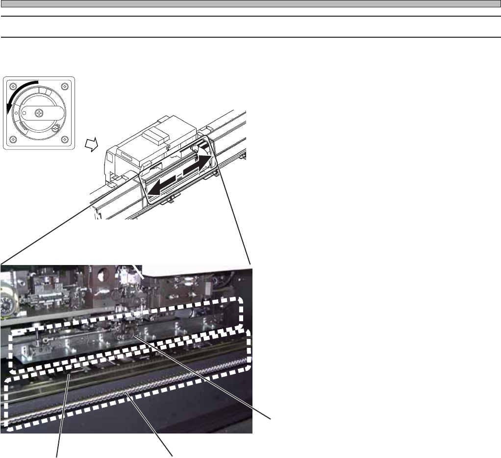
1-3-6 Cleaning the Cutting Unit (after Operation)
Clean the surroundings of cutting unit not to make it dirty.
∗ Before starting operation, carry out “Return to
origin” in the “Machine adjustment menu”
screen. If they have already been done, this is
unnecessary.
1. Turn off the power.
2. Open the rear center safety cover.
3. Clean the surroundings of cutting
unit.
∗ Check that there is no hard foreign bodies like
chips on the linear bearing rail or ball screws of
feeder drive axis.
R
E
L
E
A
S
E
T
R
I
P
O
F
F
O
N
R
E
S
E
T
Feeder drive axis
linear bearing rail
3Y3C-AI01
3Y3C-030P
3Y3C-083E
Cutting unit
Feeder drive axis
ball screw
3Y3C-E-MMD01-A03-00
Page 1-25
REGULAR
MAINTENANCE
1
3Y3C-E-MMD01-A03-00
Check Every 24 Hours (Routine)
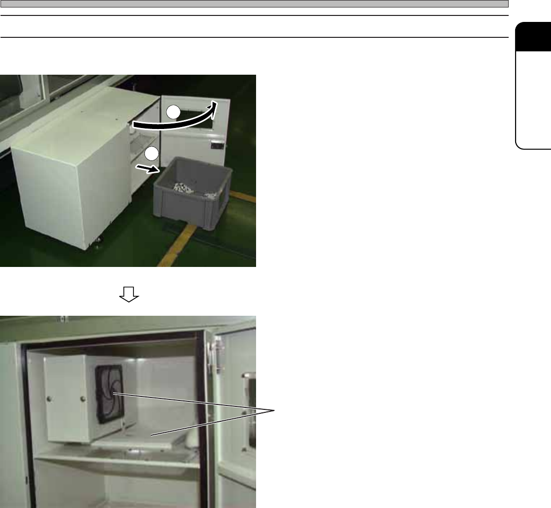
1-3-7 Blower : Cleaning the Filter
Tape cut with the cutter is gathered to the blower. Cast off this and clean the filter in the blower.
1. Open the door of blower.
2. Take out case.
3. Cast off the waste tape.
4. Clean the inside of blower with
vacuum cleaners.
∗ Clean the filter.
Filter
1
2
3Y3C-028P
3Y3C-047P
Page 1-26
3Y3C-E-MMD01-A04-01
1-4 Check Every 140 Hours (Once a Week)
1-4-1 Cleaning and Changing the Nozzles
Nozzle maintenance is described. Maintenance is mainly carried out on the rear side.
NOTICE
• As for maintenance only for the nozzle, carry out it without removing the trans-
fer head.
• Do not apply lubricating oil to the nozzle. Something adhered deteriorates the
movement of it.
• After cleaning and changing the nozzles, make sure of practicing “Nozzle
change teach.” Not doing it makes bad pickup.
∗ This section describes only the standard nozzle. For an optional nozzle, refer to “1-5-2 Nozzle
Specifications” in Operating Manual (for Engineers).
To remove and set nozzles for cleaning and changing properly, this section describes removing and
setting the same types of nozzle with all transfer heads.
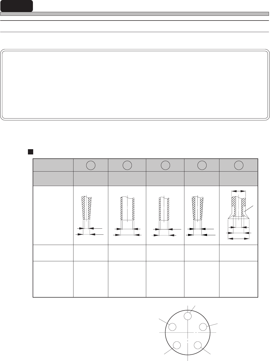
Nozzle setting
(Viewed from the top)
Big nozzle
1005
3216
2125 1608
3Y3C-042E
1
2
3
4
5
Nozzle Name
1005
16083216
Big
Shape
Pad
Recognition
types
Through Through /reflex
2125
Through
Through
Applicable
components
TAN-D
Aluminum C,D
SOP
SOJ
PLCC
1005
1608
SS-Mini Tr
SS-Mini Di
S-Mini Tr
S-Mini Di
Melf (
φ
1 to 1.5)
2125
Mini Tr
Mini Di
Melf (
φ
2.2)
3216
3225
TAN-A,B,C
Mini-P Tr
Aluminum A,B
φ
0.5
φ
0.6
φ
0.7
φ
0.9
φ
0.9
φ
1.3
φ
1.4
φ
1.8
φ
2.5
φ
4
φ
1.5
φ
3
3Y3C-036E
3Y3C-037E
3Y3C-038E
3Y3C-040E
3Y3C-041E
Through
Nozzle position
Nozzle Position
1
2 3 4 5