CM88Maintenace1.pdf - 第80页
Page 1-42 Check Every 140 Hours (Once a W eek) 11 . T urn off the servo switch. 12. Open the rear center safety cover . B. Measuring 13. Set the vacuum gauge to the nozzle, and measure the vacuum pressure. ∗ Check that t…
Page 1-41
REGULAR
MAINTENANCE
1
Check Every 140 Hours (Once a Week)
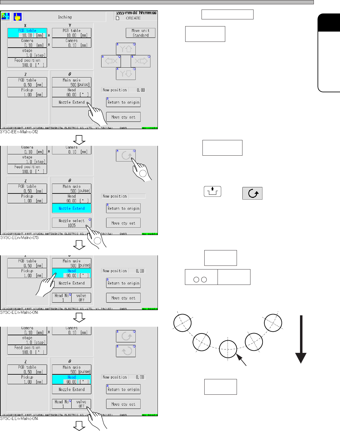
6. Press Nozzle Extend .
• appears.
7. Press .
∗ Nozzle can be optionally selected.
8. Press
UNLOCK
and .
• While the main axis goes around, the nozzle
specified at the procedure 7 is extended on all
transfer heads.
9. Press .
• are displayed.
• The number of transfer head at “Chip pickup”
station appears.
10. Press .
• The transfer head starts pickup with the
vacuum at the “Chip pickup” station.
Rear side
Main axis
Chip pickup
Nozzle select
1005
Nozzle select
1005
Head
90.00[deg]
Head No
3Y3C-084E
To the next page
3Y3C-E-MMD01-A04-01
Valve
OFF
Valve
OFF
1
2
Page 1-42
Check Every 140 Hours (Once a Week)
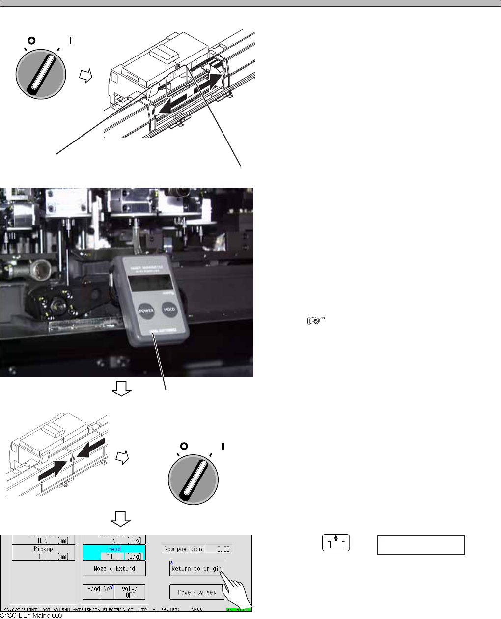
11. Turn off the servo switch.
12. Open the rear center safety cover.
B. Measuring
13. Set the vacuum gauge to the nozzle,
and measure the vacuum pressure.
∗ Check that the value is higher than the stan-
dard value, 84kPa.
∗ When the vacuum pressure is lower than the
standard value, check for the following three
items.
1. Clogged nozzle
2. Trouble of silicon tube
“1-7-2 Changing the Vacuum Silicon
Tube”
3. Other vacuum valve is turned on.
If these trouble are not found, make contact
with us.
14. Remove the vacuum gauge.
15. Close the rear center safety cover.
16. Turn on the servo switch.
17. Press
UNLOCK
and Return to origin .
• The main axis rotates by a step (Origin posi-
tion).
∗ To continue “Measuring the same types of nozzle at the all transfer heads” for other nozzles,
repeat the procedures 7 to 17 after the procedure 17 by step.
∗ For “Measuring at the optional transfer head,”
Carry out the procedure 17 after the procedure 7, and repeat the movement by step until the
optional transfer head moves to the “Chip pickup” station, then carry out the procedures 9 to 16.
∗ For “Measuring the optional nozzle,” select that nozzle at the procedure 7, and follow the proce-
dure of “Measuring at the optional transfer head.”
OFF ( )
ON ( )
SERVO
3Y3C-AI01
3Y3C-AG01
3Y3C-037P
3Y3C-E-MMD01-A04-01
OFF ( )
ON ( )
SERVO
Vacuum gauge
Page 1-43
REGULAR
MAINTENANCE
1
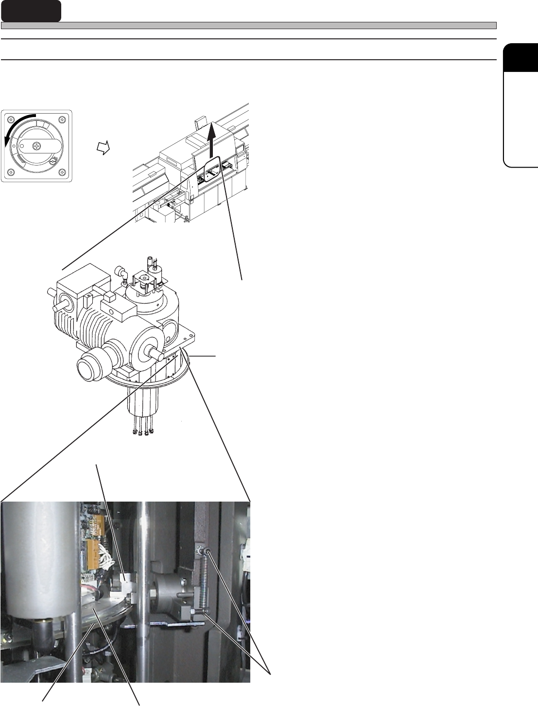
1-5 Check Every 560 Hours (Once a Month)
1-5-1 Cleaning and Greasing the Air Unit
Air unit is for mounting chip and discharging NG chip, and airing during forceful airing of nozzle.
1. Turn off the power.
2. Open the front safety cover.
3. Clean the disk of main axis with a
cloth.
4. Apply grease to the rail of disk.
(Oil : VALIANT U2)
∗ Be careful not to pour the grease to air supply-
ing section.
∗ We recommend to use a brush or spatula.
5. Clean the spring, and apply grease to
the hook.
(Oil : VALIANT U2)
R
E
L
E
A
S
E
T
R
I
P
O
F
F
O
N
R
E
S
E
T
4G3C-AB01
01DHC2AA
Main axis
Disk
Air unit
Rail part of disk
Do not apply grease to this face.
Spring hook
3Y3C-038P
3Y3C-E-MMD01-A05-02