CM88Maintenace1.pdf - 第50页
Page 1-12 Outline of Maintenance = Check = Clean = Applying or pouring grease or (change) oil = Exchange 14. T ape feeder 20. Mounting section 15. Nozzle changer 16. Height sensor 17. Feeder drive axis 19. Main body 18. …
Page 1-11
REGULAR
MAINTENANCE
1
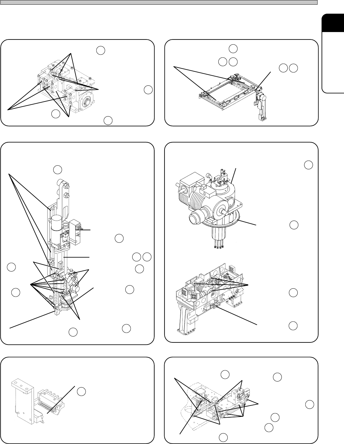
Outline of Maintenance
10. Elevating unit
12. Chip recognition section
8. Cam box 3
9. Board holder
11. Whole frame
13. Take-up section
4) Cam face
1) Cam follower
2) Lever fulcrum
3) Spring
2) Linear bearing
3) Gear
1) NG box
3) Rib cam
4) Oil for indexing device
2) Timing belt
and pulley
7) Vacuum silicon tube
1) Linear bearing
8) Vacuum change
valve
3) Nozzle retraction guide
spline shaft
1) Chip recognition camera
1) Linear bearing
4) Cam follower
2) Spline shaft
5) Spring
01DMC2AA 15ULC0AA
010KC0AA 01DVC2AA
16EYC0AA 01DPC2AA
01DHC2AA
3Y3C-E-MMD01-A01-01
2) Screw shaft
3) Cam follower
6) Spring
5) Lever fulcrum
4) Rod end
Gr
Gr
Gr
Gr
Gr
Gr
Cl
Cl
Cl
Gr
Cl
Ex
Gr
Gr
Gr
Gr
Ex
Cl
Gr
Gr
Ch
Cl
Gr
Gr
Gr
Gr
Gr
Gr
9) Bearing
Ex
6) Linear bearing
Gr
Page 1-12
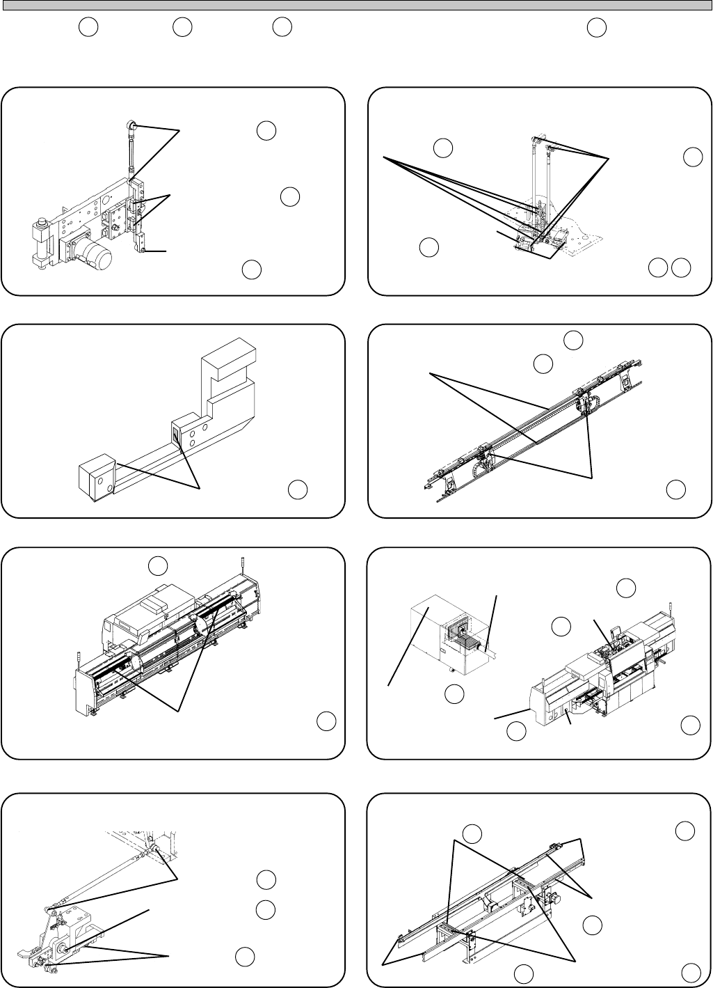
Outline of Maintenance
= Check = Clean = Applying or pouring grease or (change) oil = Exchange
14. Tape feeder
20. Mounting section
15. Nozzle changer
16. Height sensor
17. Feeder drive axis
19. Main body
18. Feeder table
3) Spring
2) Rod end
1) Linear bearing
1) Feeder table and surroundings
1) Pressure gauge
2) Blower
4) Vacuum pump
3) Spring
01DTC2AA
07JGC2AA
11DGC2AA01DQC1AA
AJ01
3Y3C-011E
010MC0AA
2) Rod end
1) Linear bearing
3) Tape feeding cam
follower
1) Lever fulcrum
1) Glass face
3) Tape discharging hose
21. Front and rear conveyor
2) Screw shaft
5) Board transfer roller
AF01
00DHC2AB
3Y3C-E-MMD01-A01-02
2) Rod end
1) Lever fulcrum
5) Board transfer roller
1) Linear bearing
4) Board transfer belt
Ch
Cl
Gr
Ex
Gr
Gr
Ex
Gr
Gr
GrCl
Ex
Cl
Ch
Gr
Gr
Ch
Cl
Cl
Ch
Ex
Ex
Gr
Gr
Gr
Gr
Gr
Ex
Ex
Ex
2) Ball screw
4) Nozzle extension
claw
Cl
5) Oil cooling box : Filter
(only for CM88S)
Page 1-13
REGULAR
MAINTENANCE
1
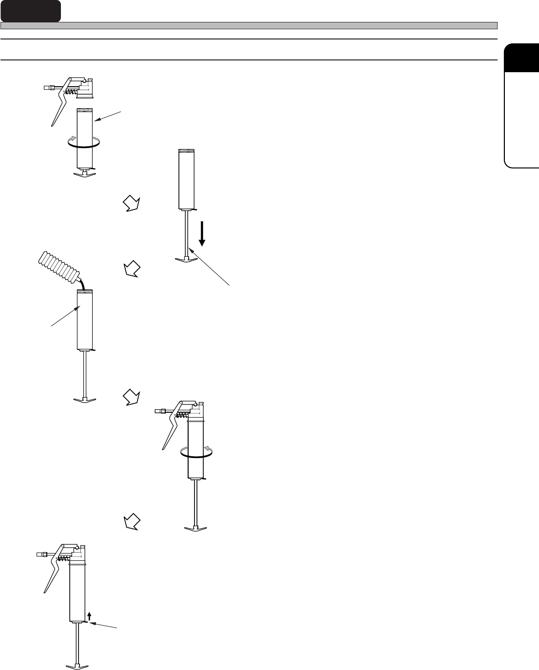
1-2 Lubricating
1-2-1 Charging the Grease Gun
1.
Unscrew the grease reservoir.
2. Pull down the piston.
3. Fill the reservoir with grease.
4. Refit the reservoir to the grease gun.
5. Release the piston stopper.
• Piston stopper is always working.
∗ The spring pushes the piston, and grease is
supplied to the top of the grease gun.
Grease reservoir
Piston (pull down)
Be careful not to
enter any air.
Tight fully.
Piston stopper
(Push upward once.)
3Y3C-E-MMD01-A02-00