KE-750_MS.pdf - 第106页
6. Bank Up Cy linder Speed Control Adjustment (Optional One-Shot Replacement Base) Lock the speed control of the right cyli nder and adjust the left speed control. (At time of assembly, close upper cylinder comple tely t…
(14) Install one-shot replacement base in main body.
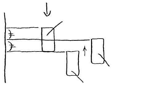
(15) Lowering the bank up detection sensor, fasten it in the gap between where the LED light goes on
and off.
LED light off
Fasten here
LED light on
Fig. 9-5-3
1-98
6. Bank Up Cylinder Speed Control Adjustment
(Optional One-Shot Replacement Base)
Lock the speed control of the right cylinder and adjust the left speed control.
(At time of assembly, close upper cylinder completely then loosened 3 turns. Close lower cylinder
completely then loosened 4 turns.)
Remove cylinder box B to open.
UP Upper speed control adjusts ascending speed
If ascending speed of left cylinder is too quick, turn adjusting screw clockwise.
DOWN Lower speed control adjusts descending speed
If descending speed of left cylinder is too quick, turn adjusting screw clockwise.
Once up & down speeds of left & right cylinders are even, use the lock screw to lock the adjusting screw.
After locking the setting, operate UP/DOWN once again to verify.
1-99
7. Bank Up Detecting Sensor Replacement
(Optional One-Shot Replacement Base)
(1) Turn main power source OFF.
(2) Follow the same procedures (2) through (7) given in section 9 - 5.
(8) Loosen mounting screw and lower to remove.
(9) Reassemble in reverse sequence.
Mounting scre
w
Fig. 9-7-1
(Adjustment)
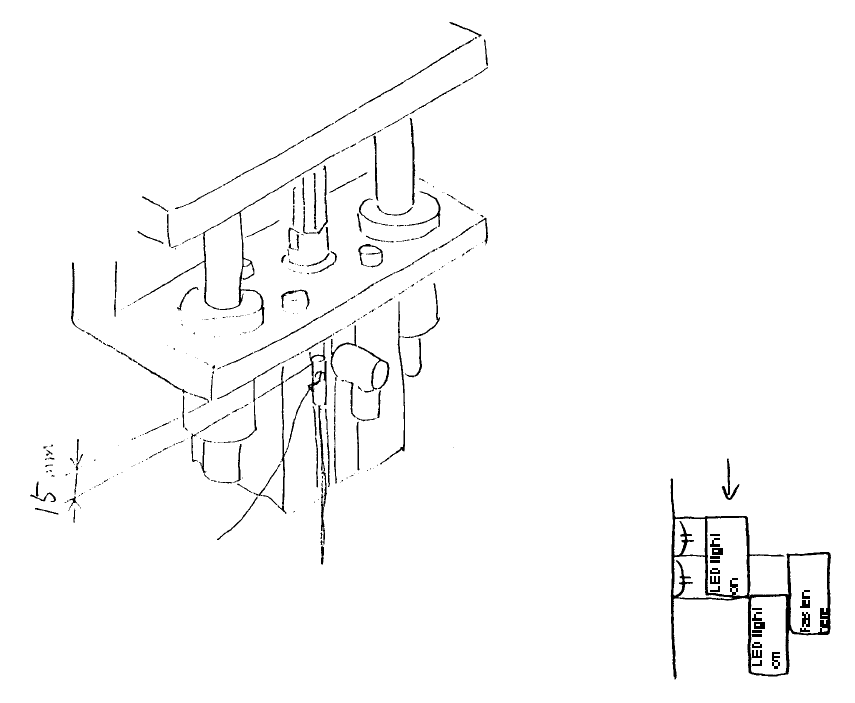
(1) Provisionally fasten cylinder 15mm from its upper max. position.
(2) Turn main power supply ON.
(3) nstall one-shot replacement base in mounter.
(4) Lowering the bank up detector sensor, fasten it in the gap between where the LED light goes on and
off.
(Bank up detector cable)
Lengths differ
Front E95577250A0
Rear E95587250A0
1-100