KE-750_MS.pdf - 第41页
12. O-Ring Replacement (1) Use a pincet or similar tool to remove O-ring fr om inside Z slider shaft taking care not to damage the inside of the shaft. (2) Insert new O-ring snugly into the shaft. (3) After replacement, …
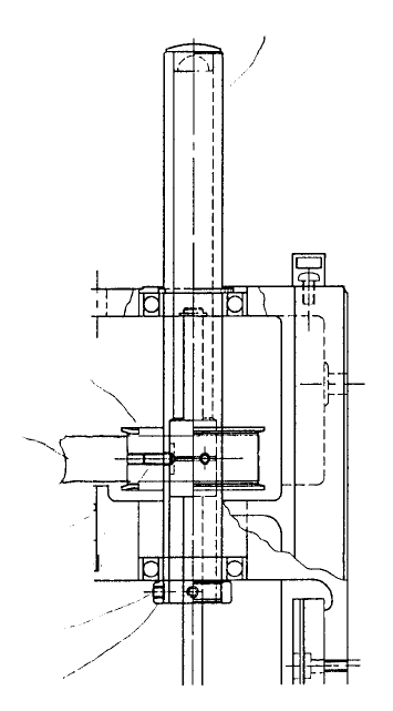
11. Spline Housing Assy Replacement
To replace spline housing (IC) assy, it is necessary to loosen tension on timing belt
and disconnect the spline shaft side of coupling θ. All the various operations for Z-axis motor
replacement and coupling θ replacement must be carried out including the required adjustments.
Since θ positioning upon home return is automatically the θ-axis home, no adjustment is necessary.
Reentry of MS parameters is also not required.
(1) Loosen tension of timing belt θ. (Refer to section 2- 3 Z-axis motor replacement.)
(2) Disconnect coupling θ on spline shaft side only. (Refer to section 2 - 8 Coupling θ replacement.)
(3) Loosen the 2 screws in sheeter pulley until sheeter pulley rotates freely.
(4) Loosen the 2 screws in spline thrust coupler and remove spline housing (IC) assy.
(5) Reassemble in reverse sequence. Afterwards, check spline housing Z direction. (Refer to QA Table,
Head, Spline housing Z direction.)
Ref No. 5 “Z-direction play inspline housing”
Stop scre
w
Spline thrust
collar
Stop scre
w
Timing belt θ
Sheeter pulle
y
Spline housing (IC) ass
y
Fig. 2-11-1
1-34
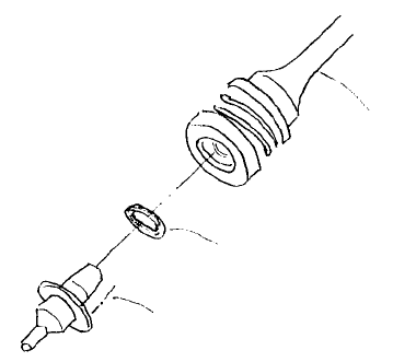
12. O-Ring Replacement
(1) Use a pincet or similar tool to remove O-ring from inside Z slider shaft taking care not to damage the
inside of the shaft.
(2) Insert new O-ring snugly into the shaft.
(3) After replacement, lightly coat the contact surface of the nozzle to the O-ring with grease and
join/separate with shaft several times to coat O-ring.
Greased surface
O-ring
Z slider shaft
Fig. 2-12-1
1-35

13. Summary of Readjustments Required after Replacement
- Enter MS parameters in the order given above starting at the top. (Refer to MS parameter control
specifications.)
Head unit
assy
Z slider
shaft assy
Z-axis
motor assy
θ-axis
motor assy
Laser
sensor
Coupling
Z
Spline housing
assy
Head centering
{
Z-axis home adjust
{
{
θ belt tension adjust
{
{
Laser offset
{ { {
{ {
Laser scaling
{ {
{
VCS camera offset
VCS general offset*
{ {
ATC
Nozzle Setup
{ {
{
Vacum value
without Nozzle
{ {
Head offset
{ {
{
(*) Note: Only applies to LAIC head.
1-36