KE-750_MS.pdf - 第91页
3. 0.4/0.3 VCS Light PWB Assy Replacement (1) Disconnect cable from PWB connector (2) Loosen the 4 Allen head screws. Push so t hat spacers do not fall and remove diffuser. (Refer to Dia. 10 - 1 - (1) if there are diffic…
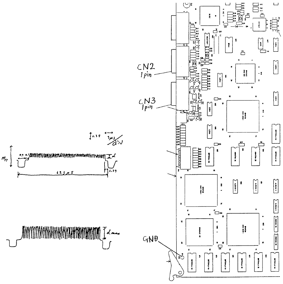
5) Connect IMG-P PWB assy to an
oscilloscope. To focus the camera on
the VCS(0.4) assy, connect CN2 1 pin
to GDN as shown at right.
To focus the camera on the VCS(0.3)
assy, connect CN3 1 pin to GDN.
6) While watching the oscilloscope, turn
the upper part of the lens until the
maximum band width appears. After
lens adjustment, tighten any one of the
4 screws in the lens.
(B) After adjustmen
t
(A) Before adjustmen
t
A
djust focus when d value is at
max.
Note: In reality, blank spaces blu
r
the wave form.
Fig. 8-2-3 Fig. 8-2-2
1-83
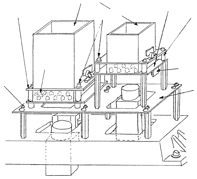
3. 0.4/0.3 VCS Light PWB Assy Replacement
(1) Disconnect cable from PWB connector
(2) Loosen the 4 Allen head screws. Push so that spacers do not fall and remove diffuser.
(Refer to Dia. 10 - 1 - (1) if there are difficulties. Remove light base and continue.)
M3 SEMS
screw
Light base
Connecto
r
Space
r
0.3 VCS light PWB ass
y
A
llen head scre
w
Diffuse
r
0.4 VCS light PWB ass
y
Fig. 8-3-1
1-84
(3) Transfer cover glass to the new board. (Refer to section 10 - 4.)
(4) Be careful with PWB connector orientation. Assemble by following step (2) in reverse sequence.
(5) Connect cables.
(6) For information on adjusting brightness, refer to QA Table, Electricals, EL-11, 0.4 VCS / 0.3 VCS
Light Map.
1-85