KE-750_MS.pdf - 第81页
Chapter 7 ATC Unit 1. Air Cylinder Replacement (1) Close hand valve at the lower right of main body. (2) Remove the 2 M6 SEMS cap screws to separate support angle from main body. (3) Remove ATC and M3 SEMS cap screw and …
(5) Replace silencer and elbow union. Take careful note of solenoid valve tap hole numbering.
[E] - Silencer
[A], [P] - Elbow union
(6) Follow steps (1) ~ (5) in reverse sequence to reassemble.
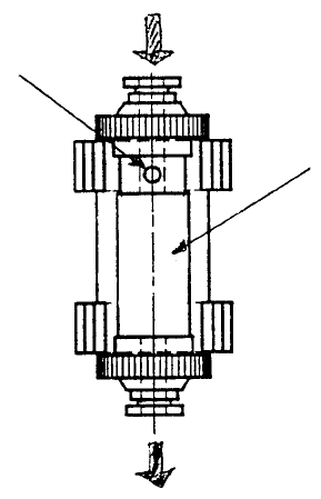
4. Union Filter Replacement
The union filter is replaced by removing it from the holder and separating the air tube. When replacing
with a new filter, be sure the orientation is correct.
to Ejecto
r
Union
Hole
from CAL plate
Fig. 6-4-1
1-73
Chapter 7 ATC Unit
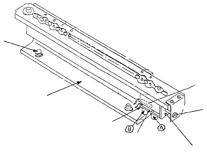
1. Air Cylinder Replacement
(1) Close hand valve at the lower right of main body.
(2) Remove the 2 M6 SEMS cap screws to separate support angle from main body.
(3) Remove ATC and M3 SEMS cap screw and remove air cylinder (Detach φ4 air tube).
(4) Attach ATC OPN & CLS sensor assemblies straight onto the new air cylinder.
ATC CLS
sensor assy
A
TC OPN sensor ass
y
A
TC join
t
M3 SEMS cap scre
w
A
ir cylinde
r
A
TC support angle
M6 SEMS cap
screw
Fig. 7-1-1
1-74
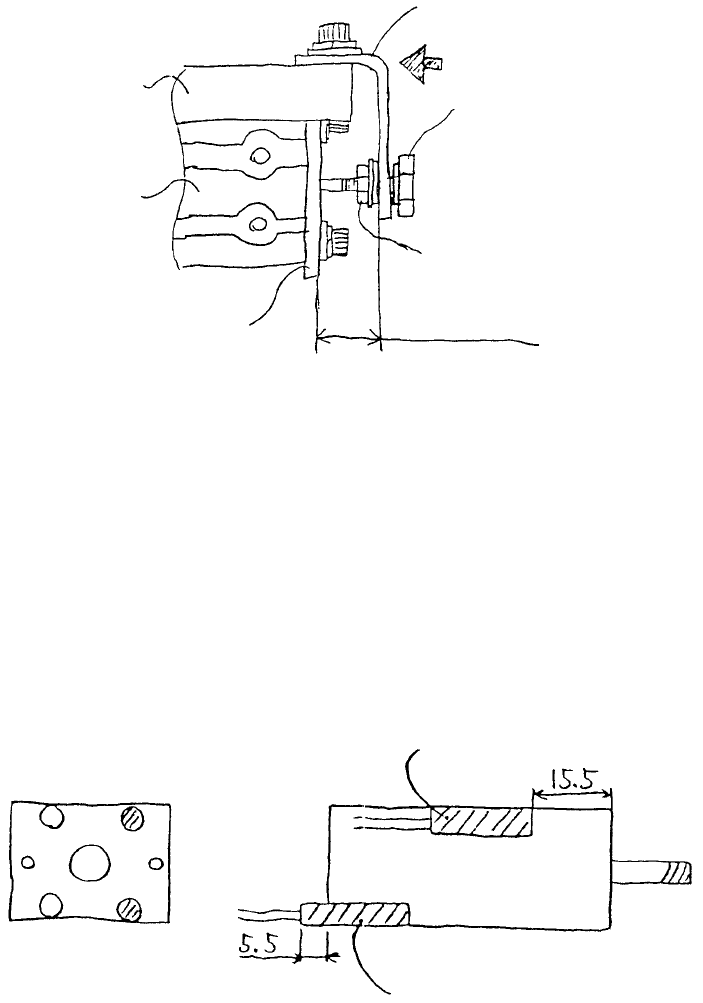
(5) ATC cylinder & sensor adjustment
a. ATC cylinder adjustment
When pressed
A
TC angle
A
TC join
t
Locktite 242
6.7 ± 0.5mm
A
TC cylinder accessory nut
A
TC base
(730/740)
A
TC cylinde
r
Slide plate
(730/740)
Fig. 7-1-2
When slide plate is pressed together as shown above, set distance from ATC base to ATC angle
at 6.7±0.5mm by adjusting ATC joint with cylinder accessory nut. At this time coat the threads
with Locktite 242.
b. Sensor positioning adjustment
A
TC OPN sensor ass
y
A
TC CLS sensor ass
y
Note 1: Be sure there is rubber in the tip of the sensor fastening screw.
Note 2: Tighten fastening screw to torque 1~2kgf•cm.
1-75