KE-750_MS.pdf - 第43页
Chapter 3 Head Periphery 1. Vacuum Sw itch Solenoid Replacement As the vacuum switching solenoid continuously supplies the main body from the pressure source, replace after main body pressure has fallen. Note: For model …

13. Summary of Readjustments Required after Replacement
- Enter MS parameters in the order given above starting at the top. (Refer to MS parameter control
specifications.)
Head unit
assy
Z slider
shaft assy
Z-axis
motor assy
θ-axis
motor assy
Laser
sensor
Coupling
Z
Spline housing
assy
Head centering
{
Z-axis home adjust
{
{
θ belt tension adjust
{
{
Laser offset
{ { {
{ {
Laser scaling
{ {
{
VCS camera offset
VCS general offset*
{ {
ATC
Nozzle Setup
{ {
{
Vacum value
without Nozzle
{ {
Head offset
{ {
{
(*) Note: Only applies to LAIC head.
1-36
Chapter 3 Head Periphery
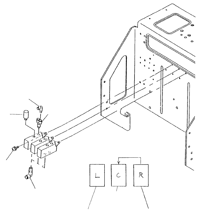
1. Vacuum Switch Solenoid Replacement
As the vacuum switching solenoid continuously supplies the main body from the pressure source,
replace after main body pressure has fallen.
Note: For model 760 use a right head solenoid in the
center solenoid position.
Head 2 vacuum
ON cable assy
E93177250A0
Head 1 vacuum
ON cable assy
E93147250S0
Head 3 vacuum
ON cable assy
E93207250A0
Note: Only for model 760
Elbow union
PJ304040505
SEMS scre
w
SL4030881SL
Branch
PJ308065101
Silence
r
PX058001000
Reducer elbo
w
PJ304040004
Fig. 3-1-1
1-37
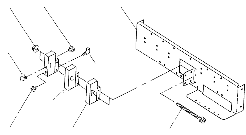
2. Blow Switch Solenoid Replacement
As the vacuum switching solenoid continuously supplies the main body from the pressure source,
replace after main body pressure has fallen.
Since the blow solenoids are the connector type they are the same for left, right & center. Be careful not
to connect incorrectly. After replacement operate manually to check head blow ON/OFF connections.
SEMS scre
w
SL4034091SC (750)
SL4033091SC (760)
A
ir mount plate
E2501725000
Elbow union
PJ304040511
Support solenoid
PY140507000
Only fo
r
model 750
Plug
PJ020500002
Elbow union
PJ304040511
Plug
PJ020500002
Flangeli
t
NM3034000SF
Fig. 3-2-1
1-38