KE-750_MS.pdf - 第149页
9. Head Unit 9-1 Head Unit Structure Structure of the head unit is shown in Fig. 17-9-1. Head main PWB assy (KE-750/760) and head motor PW B assy (KE-750) or just head motor PWB A assy (KE-760) are attached to the back o…
8-2 Conveyor Unit PWB Assy Adjustment
The CARRY PWB assy jumpers of the conveyor unit are already set upon receival but confirm when
setting PWB assy.
Refer to the PWB assy diagram below for jumper settings.
E86177210A0 CARRY PWB assy
8-3 Stepping Motor / Sensor Adjustment
Use a stepping motor for conveyor centering. For the stepping motor to achieve the proper RPM's, it is
necessary to adjust the 5 phase step driver.
HM001320000 5 phase stepping driver
For method of adjustment, refer to QA Table, Electricals, EL5~7.
1-133
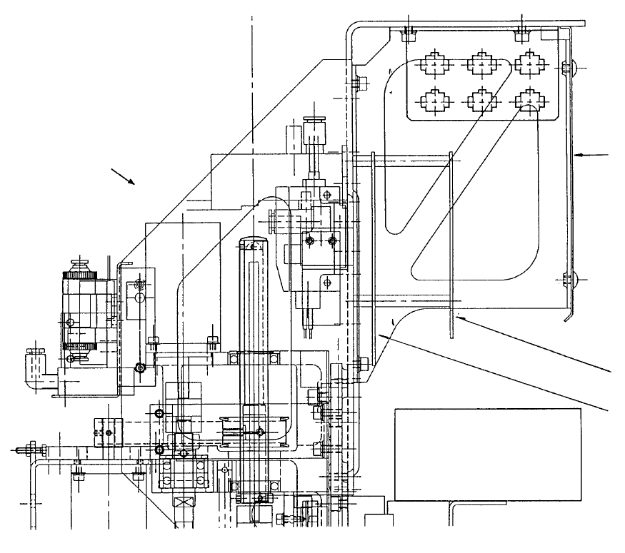
9. Head Unit
9-1 Head Unit Structure
Structure of the head unit is shown in Fig. 17-9-1.
Head main PWB assy (KE-750/760) and head motor PWB assy (KE-750) or just head motor PWB A
assy (KE-760) are attached to the back of the head unit.
X-axis puller rail
Head main
PWB assy
Head moto
r
PWB assy
Rear cove
r
Head front side
Fig. 17-9-1
1-134
9-2 Head PWB Adjustment
Head motor PWB assy and head main PWB assy jumpers used in the head unit are already set upon
receival but confirm when setting PWB assy.
Refer to the PWB assy diagram below for jumper settings.
E86077210A0 Head main PWB assy (Common)
E86057250A0 Head motor PWB assy (KE-750)
E8605725AA0 Head motor PWB A assy (KE-760)
E86517210A0 Height PWB assy (Optional)
Adjustment of the head main PWB vacuum sensor is also required. For instructions, refer to QA Table,
Electricals, EL-8.
1-135