KE-750_MS.pdf - 第129页
Power Unit Wiring Diagram 1-121
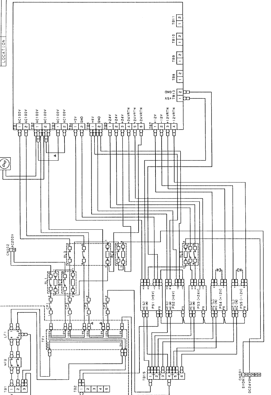
Power Unit Wiring Diagram
1-121
4. Control Unit
4-1 Control Unit Structure
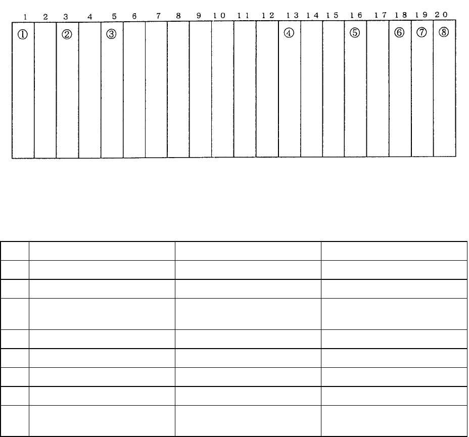
Dia. 17 - 4 - 1 shows PWB distribution in the control unit and Table 17 - 4 - 1 provides the relevant part
numbers. Refer to these to check the PWB assy.
Slot No. 20 Slots
Fig. 17 - 4 - 1 PWB Wiring Diagram (Front view of rack)
Table 17-4-1 Correlation of Parts Numbers
No. Part No. PWB Assy Name Comments
1 E86017210A0 Sub CPU PWB assy (Main)
2 E86027210A0 AC servo control PWB assy
3 E86017250A0
E8601725AA0
Z/θ control PWB assy
Z/θ control PWB A assy
For KE-750
For KE-760
4 E86057210A0 I/O control PWB assy
5 E86317210A0 MATCHING PWB assy
6 E86107210A0 IMG-P PWB assy
7 E86717050A0 VERFY I/F PWB assy Optional
8 E9710721000
(Accessory PWB)
L.L.L PWB Optional
Note: PWB assemblies (5) & (6) should only be connected to the slots indicated in Dia. 17 - 4 - 1.
Improper connection will result in the damage of IC's in every PWB when power is supplied.
1-122