KE-750_MS.pdf - 第207页
Once completed, select "OK". Selecting "OK" moves OCC to CAL block No. 2 mark. With teaching adjust the monitor cross hair cursor so that it falls near the center of the No. 2 mark and press HOD Enter…
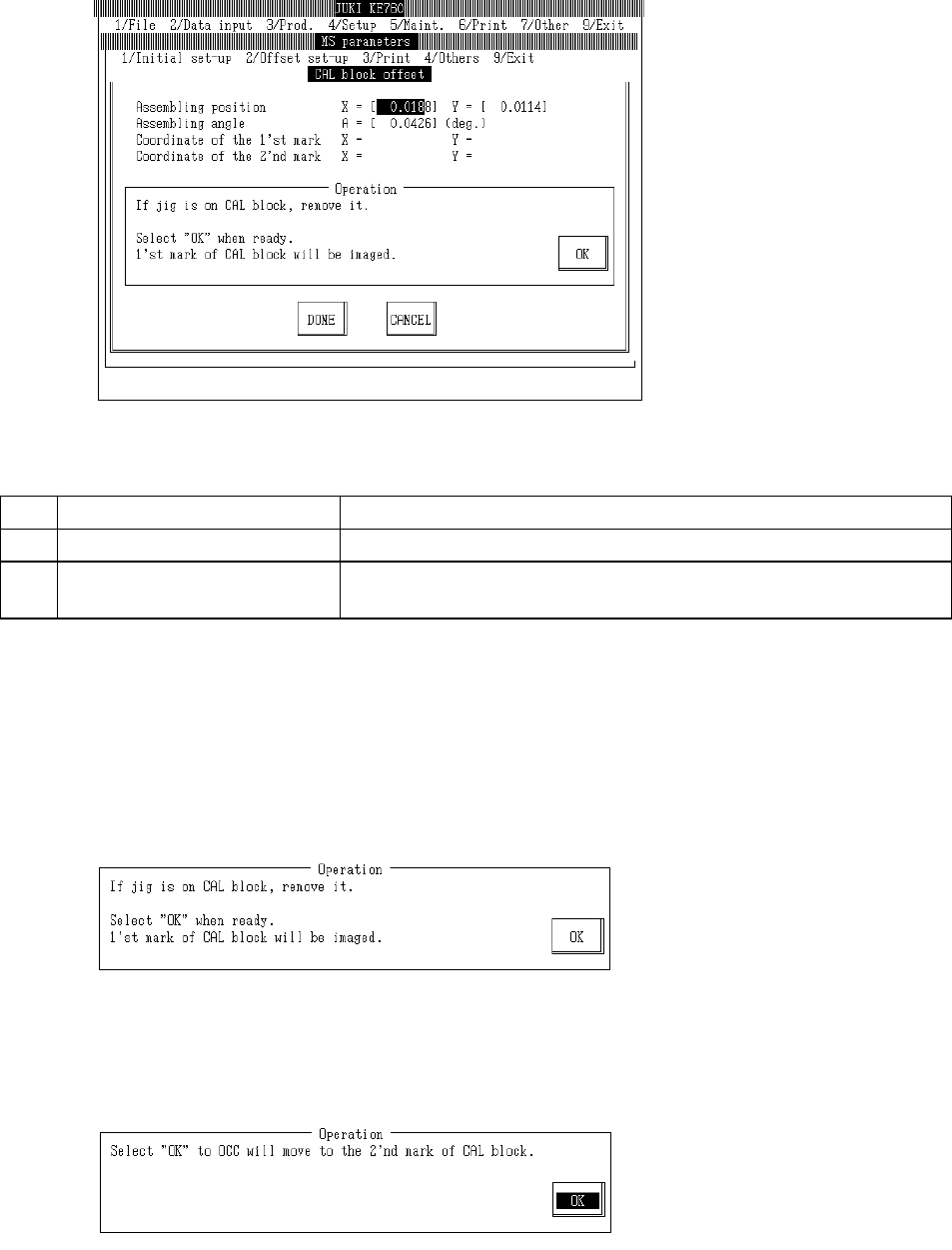
4.10 CAL Block Offset
Select "2/Offset set-up" then "2/CAL Block Offset", and the CAL block setting dialog will appear as
follows.
(1) Setting Items
No. Item Contents
1 Assembling Position Offset value based on calculated CAL block center position
2 Assembling Angle Assembling angle between CAL block & main body (main body as base)
(° )
(2) Method of Setting
– Follow operating directions for automatic input.
– Use control menu to move head if in the way.
– Select HOD device key to enter teaching.
– Operating method of automatic input
Follow instructions to operate and values will automatically acquire.
If jig is above CAL block, remove jig.
Once completed, select "OK".
Selecting "OK" causes acquired coordinates to appear when OCC recognizes the CAL block No.
1 mark.
2-39
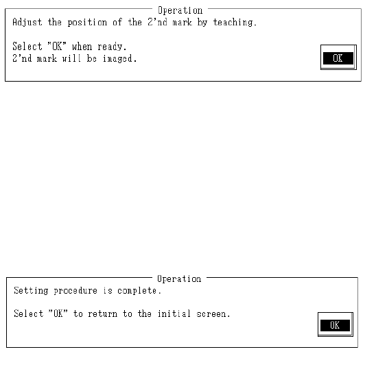
Once completed, select "OK".
Selecting "OK" moves OCC to CAL block No. 2 mark.
With teaching adjust the monitor cross hair cursor so that it falls near the center of the No. 2
mark and press HOD Enter key.
If no adjustment is needed, teaching is not required.
Once completed, select "OK".
Select "OK" and when OCC will recognize CAL block No. 2 mark position, acquired coordinates
will appear.
From the acquired coordinates of the No. 1 & 2 marks, offset and inclination of CAL block central
coordinates are calculated and modified.
Setting is completed.
Select "OK" to return to default operation screen.
2-40
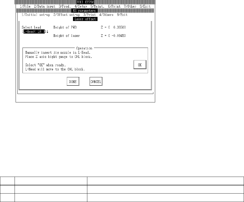
4.11 Laser Offset
4.11.1 Laser Offset
Select "2/Offset set-up" then "3/Laser", "1/Laser Offset" and the laser offset setting dialog will appear
as follows.
– Setting Head
The head to be set is selected from the combination box.
Press "Alt" + " " keys and the following overview will appear.
This does not affect the "Unit Available" setting in machine setup. (Can also be selected for
units not checked "Unit Not Available".)
(1) Setting Items
No.
Item Contents
1 Board Surface Height Offset value for Z axis board surface height setting value
2 Laser Height Offset value for Z axis laser height setting value
(2) Method of Setting
Head is selected with tuning button. For head selected, enter values directly with the keyboard
or follow the internal operating instructions for automatic input.
– Select HOD device key to enter teaching.
– Use control menu to move head when it is in the way.
2-41