KE-750_MS.pdf - 第98页
(5) Replace with new drive cylinder oriented upside-down as in Dia. 9 - 1 - 3. Note: Work from the even surface of the table or the top of the bank. – Mount so there is no gap between left & right cylinders (Dia. 9 -…
1. Drive Cylinder Replacement (Refer to Dia. 9 - 1 - 1)
(1) Turn main power source OFF.
(2) Shut off main air supply (hand valve).
(If the optional one-shot replacement base is used, disconnect and remove it from the main body.
Turn sensor and left / right roller lever ON. Raise bank lifter and shut off air.)
(3) Disconnect left / right air tubes (1) and connectors (2).
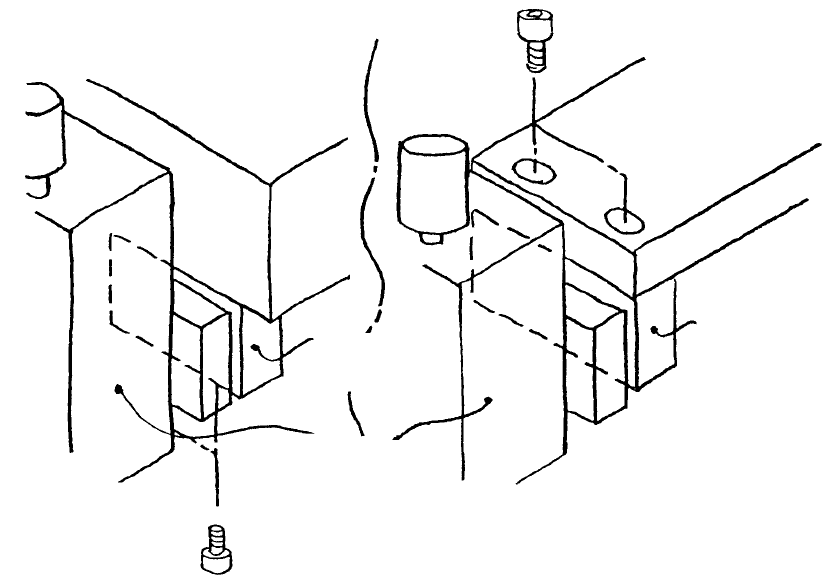
(4) Remove screws holding driver bracket support.
– For standard layout, driver bracket support A is attached through the bottom to the bottom of the
bank.
– For the one-shot replacement base, the driver bracket support B is attached through the top of
the bank lifter.
Driver bracket
support B
Drive cylinde
r
Driver bracket
support A
Bank lifte
r
Ban
k
(Standard) (One-shot replacement base)
Fig. 9-1-2
1-90
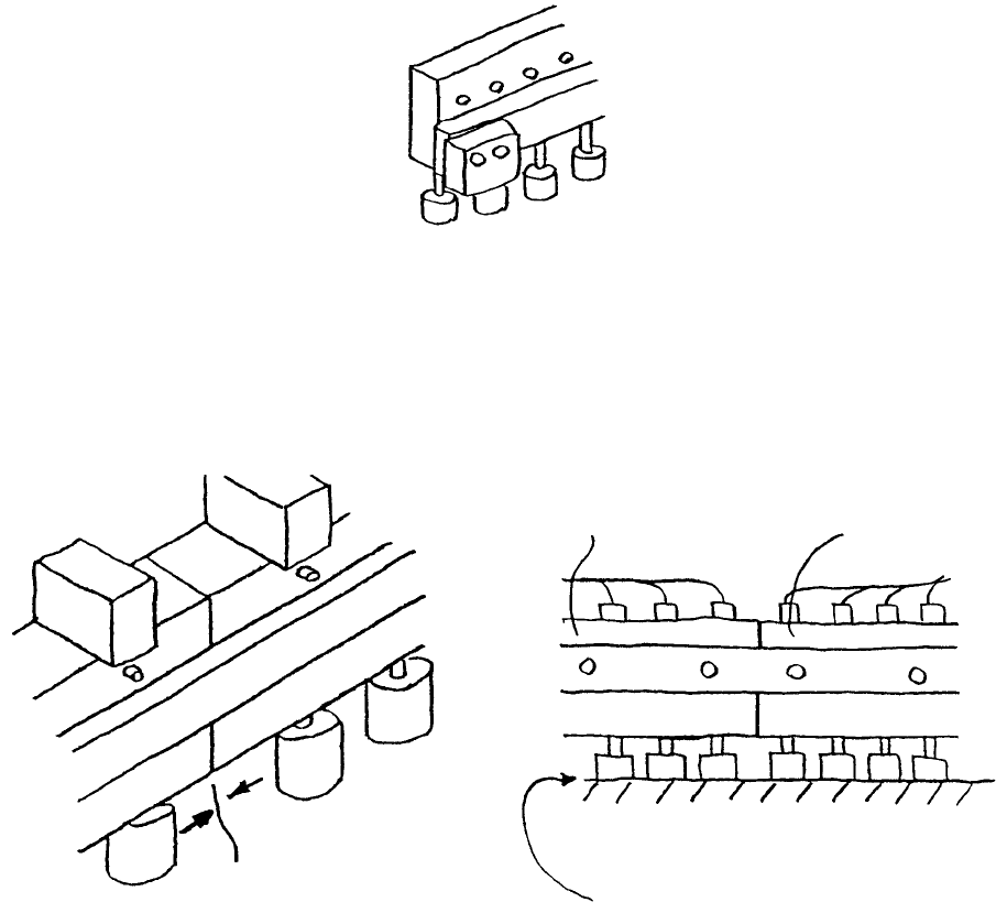
(5) Replace with new drive cylinder oriented upside-down as in Dia. 9 - 1 - 3.
Note: Work from the even surface of the table or the top of the bank.
– Mount so there is no gap between left & right cylinders (Dia. 9 - 1 - 3, Dia. 9 - 1 - 4).
– Mount so there is minimal gap between bank top surface and up/down cylinders (Dia. 9 - 1 - 5).
Fig. 9-1-3
Only replace left & right cylinders one at a time.
Previously mounted
cylinder
Bank top surface
No gap
No gap
Replaced cylinde
r
Fig. 9-1-4 Fig. 9-1-5
(6) Reassemble in reverse sequence.
1-91
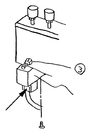
2. Drive Cylinder Solenoid Valve Replacement
(1) Press at point indicated by arrow and pull down to remove cable.
(2) Remove the 2 screws holding solenoid and remove solenoid.
(3) Mount new solenoid valve.
(4) Insert cable and press firmly until it clicks.
Solenoid valve
Fig. 9-2-1
1-92