KE-750_MS.pdf - 第82页
(5) ATC cylinder & sensor adjustment a. ATC cylinder adjustment When pressed A TC angle A TC join t Locktite 242 6.7 ± 0.5mm A TC cylinder accessory nut A TC base (730/740) A TC cyli nde r Slide plate (730/740) Fig. …
Chapter 7 ATC Unit
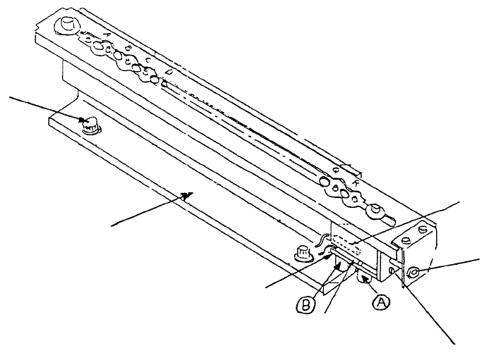
1. Air Cylinder Replacement
(1) Close hand valve at the lower right of main body.
(2) Remove the 2 M6 SEMS cap screws to separate support angle from main body.
(3) Remove ATC and M3 SEMS cap screw and remove air cylinder (Detach φ4 air tube).
(4) Attach ATC OPN & CLS sensor assemblies straight onto the new air cylinder.
ATC CLS
sensor assy
A
TC OPN sensor ass
y
A
TC join
t
M3 SEMS cap scre
w
A
ir cylinde
r
A
TC support angle
M6 SEMS cap
screw
Fig. 7-1-1
1-74
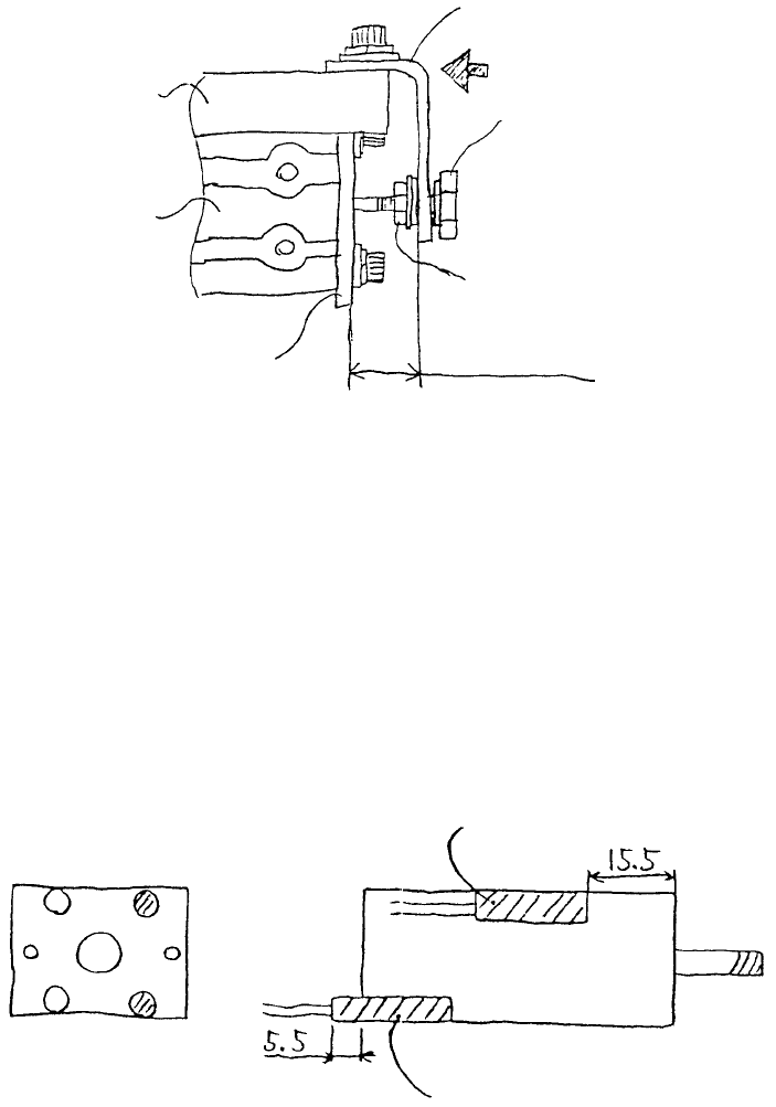
(5) ATC cylinder & sensor adjustment
a. ATC cylinder adjustment
When pressed
A
TC angle
A
TC join
t
Locktite 242
6.7 ± 0.5mm
A
TC cylinder accessory nut
A
TC base
(730/740)
A
TC cylinde
r
Slide plate
(730/740)
Fig. 7-1-2
When slide plate is pressed together as shown above, set distance from ATC base to ATC angle
at 6.7±0.5mm by adjusting ATC joint with cylinder accessory nut. At this time coat the threads
with Locktite 242.
b. Sensor positioning adjustment
A
TC OPN sensor ass
y
A
TC CLS sensor ass
y
Note 1: Be sure there is rubber in the tip of the sensor fastening screw.
Note 2: Tighten fastening screw to torque 1~2kgf•cm.
1-75
(6) Connect φ4 air cylinder. Open hand valve bit by bit until air comes out and connect at location (B) in
Fig. 7 - 1 - 1. Connect another at location (A).
(7) Follow (2) in reverse sequence to connect (only tighten screw provisionally).
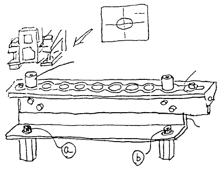
(8) Set ATC offset boss assy (jig) in the 2 holes as shown below.
While looking at the live image of the OCC camera, move head with HOD until one of the ATC is
nearly centered in the CRT.
A
TC
A
TC support angle
A
TC offset boss ass
y
(Head)
Fig. 7-1-4
Next, move HOD along X-axis (Do not move in Y-axis) until the other offset boss can be seen.
Loosen screws (a) & (b) and move ATC with ATC support angle until the boss is nearly centered in
the CRT.
Repeat this procedure with the 2 bosses until Y-axis displacement is to within 0.1mm at both ends
and then tighten screws (a) & (b).
Since camera aperture is 6.3mm and boss diameter is 2.5mm, a visual judgement must be made.
(9) Reenter MS parameters of ATC offset.
1-76