KE-750_MS.pdf - 第93页
4. BGA Light PCB Assy Replacement (1) Remove BGA light cable assy connec tor from BGA/CSP relay cable assy. (2) Grasp VCS diffuser A1 and pull upwards to remove. (3) Remove the 4 truss screws holding diffuser cover. (4) …
(3) Transfer cover glass to the new board. (Refer to section 10 - 4.)
(4) Be careful with PWB connector orientation. Assemble by following step (2) in reverse sequence.
(5) Connect cables.
(6) For information on adjusting brightness, refer to QA Table, Electricals, EL-11, 0.4 VCS / 0.3 VCS
Light Map.
1-85
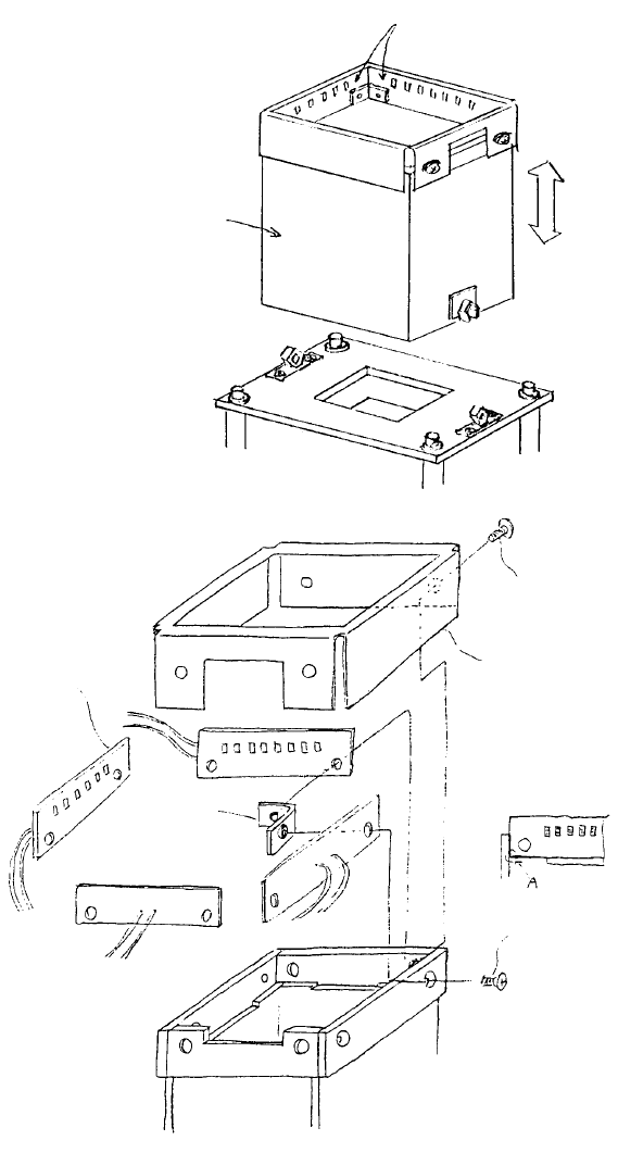
4. BGA Light PCB Assy Replacement
(1) Remove BGA light cable assy connector from BGA/CSP relay cable assy.
(2) Grasp VCS diffuser A1 and pull upwards to remove.
(3) Remove the 4 truss screws holding diffuser cover.
(4) Remove the 4 plate screws and replace BGA light cable assy.
(5) Follow steps (1) ~ (4) in reverse sequence to reassemble.
VCS diffuser A1
E3706725000
Plate screw x 4
SM1030601SC
Note: Align BGA light PWB
with edge A and fasten.
Diffuser cove
r
E3709725000
Truss screw x 4
SM0030601sc
Note: Remove BGA ligh
t
PWB assy wire bundle from
VCS diffuser by pulling at
the separation section.
BGA ligh
t
support
BGA light PWB ass
y
VCS diffuser A1
BGA light cable ass
y
(BGA light PWB assy)
1-86
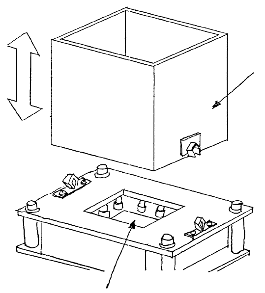
5. Cover Glass Cleaning / Replacement
(1) Cover glass cleaning
a. Grasp VCS diffuser and pull strongly to remove.
b. Wipe cover glass with a soft cloth.
c. Reconnect VCS diffuser.
Cover glass
VCS diffuse
r
Fig. 8-4-1
1-87