KE-750_MS.pdf - 第224页
4.13.3 VCS Camera Offset Select "2/Offset set-up" then "5/VCS", "3/VCS Camera Offset" and the VCS camera offset setting dialog will appear as follows. (1) Setting Items No. Item Contents 1 A…
When measurement is completed, the calculated result of X direction mark pitch is displayed.
The X direction scaling value is calculated from input values and measurement results.
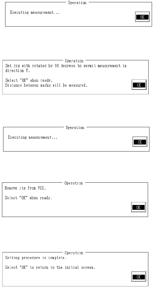
Rotate VCS jig plate B 90 in order to measure in Y direction.
Once completed, select "OK".
When "OK" is selected, Y direction mark pitch is measured with VCS.
When measurement is completed, the result of Y direction mark pitch measurement appears. Y
direction scaling is calculated from input values and measurement result and modification made.
Remove VCS plate B from VCS-HT jig.
Remove 0.3mm adaptor from VCS-HT jig when setting 0.3mm VCS.
Remove VCS-HT jig from VCS and select "OK".
Setting is completed.
Select "OK" to return to default operation screen.
2-56
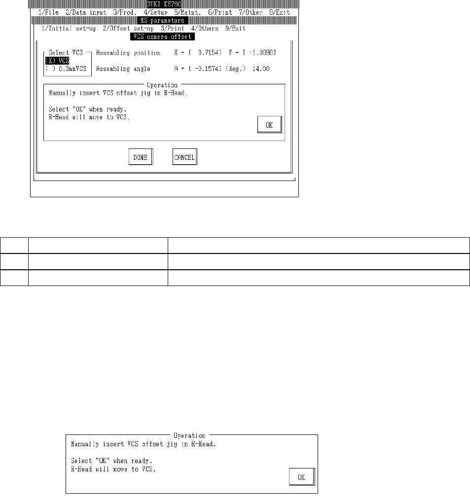
4.13.3 VCS Camera Offset
Select "2/Offset set-up" then "5/VCS", "3/VCS Camera Offset" and the VCS camera offset setting
dialog will appear as follows.
(1) Setting Items
No. Item Contents
1 Assembling position Offset value from VCS camera setting position
2 Assembling angle Assembling angle of camera (in reference to main body) (° )
(2) Method of Setting
– Select VCS unit with the tuning button and enter values directly with the keyboard or follow
the internal operating instructions for automatic input.
– Select HOD device key to enter teaching.
– Use control menu to move head if in the way.
– Operating method of automatic input
Follow instructions to operate and values will automatically acquire.
Set VCS-HT jig in LAIC head.
Once completed, select "OK".
When "OK" is selected, AIC head moves to recognition position.
2-57
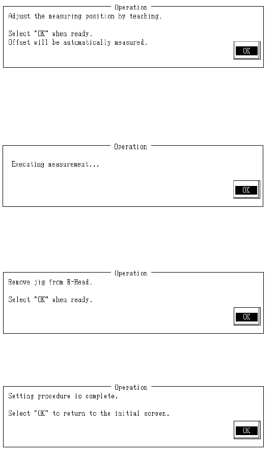
Adjust monitor cross cursor with teaching so that mark is nearly centered and press HOD Enter
key.
Once completed, select "OK".
Selecting "OK" measures offset.
When measurement is completed, assembling angle and assembling position are calculated
from the measurement result and modifications made.
From the obtained offset, move mark to VCS center.
Remove VCS offset jig from LAIC head.
Once completed, select "OK".
Setting is completed.
Select "OK" to return to default operation screen.
2-58