KE-750_MS.pdf - 第39页
10. IC Head Encoder Replacement Since the θ positioning upon home return is automatically the -axis home, no adjustment is necessary. Reentry of MS parameters is also not required. (1) Disconnect encoder wire bundle from…
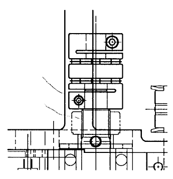
9. Coupling Z Replacement
Since Z-axis motor must be removed to replace coupling Z, afterwards, Z-axis home positioning must be
adjusted and Z-axis height and laser related MS parameters must be reentered. (Refer to section 2 - 13
for reentry.)
(1) Remove motor as directed in section 2 - 3.
(2) Loosen screw (1) and remove coupling.
(3) To mount, place coupling all the way onto ball screw and tighten screw.
(4) Mount motor as directed in section 2 - 3.
Ball scre
w
Scre
w
M2.5
Fig. 2-9-1
1-32
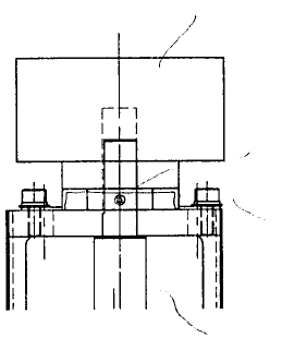
10. IC Head Encoder Replacement
Since the θ positioning upon home return is automatically the -axis home, no adjustment is necessary.
Reentry of MS parameters is also not required.
(1) Disconnect encoder wire bundle from head motor PCB.
(2) Loosen screw (2), remove the 2 SEMS caps (1) and remove encoder.
(3) When mounting, align encoder axis with spline housing IC axis and fasten SEMS caps (1). (Refer
to QA Table, Head, Encoder alignment.)
(4) Line up spline housing IC screw and tighten.
Spline housing IC
SEMS cap scre
w
Stop scre
w
Encode
r
Fig. 2-10-1
1-33
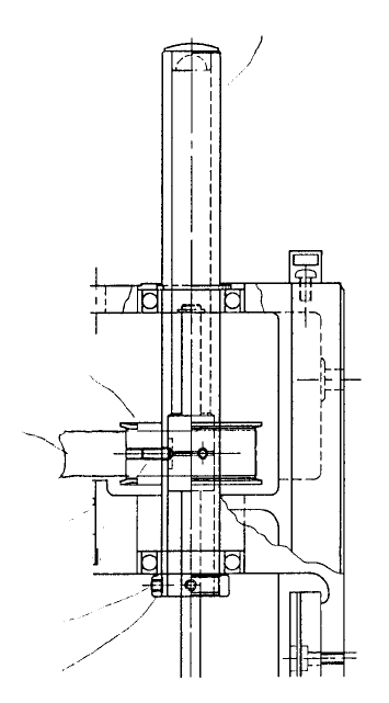
11. Spline Housing Assy Replacement
To replace spline housing (IC) assy, it is necessary to loosen tension on timing belt
and disconnect the spline shaft side of coupling θ. All the various operations for Z-axis motor
replacement and coupling θ replacement must be carried out including the required adjustments.
Since θ positioning upon home return is automatically the θ-axis home, no adjustment is necessary.
Reentry of MS parameters is also not required.
(1) Loosen tension of timing belt θ. (Refer to section 2- 3 Z-axis motor replacement.)
(2) Disconnect coupling θ on spline shaft side only. (Refer to section 2 - 8 Coupling θ replacement.)
(3) Loosen the 2 screws in sheeter pulley until sheeter pulley rotates freely.
(4) Loosen the 2 screws in spline thrust coupler and remove spline housing (IC) assy.
(5) Reassemble in reverse sequence. Afterwards, check spline housing Z direction. (Refer to QA Table,
Head, Spline housing Z direction.)
Ref No. 5 “Z-direction play inspline housing”
Stop scre
w
Spline thrust
collar
Stop scre
w
Timing belt θ
Sheeter pulle
y
Spline housing (IC) ass
y
Fig. 2-11-1
1-34