KE-750_MS.pdf - 第37页
7. Head Up Spring Replacement Remove head up spring (4) from spring stud (3) and replace. (Dia. 2 - 1 - 1~3) 8. Coupling θ Replacement (1) Loosen the 2 screws (1), (2) in coupling θ and remove coupling. (2) To mount, ins…
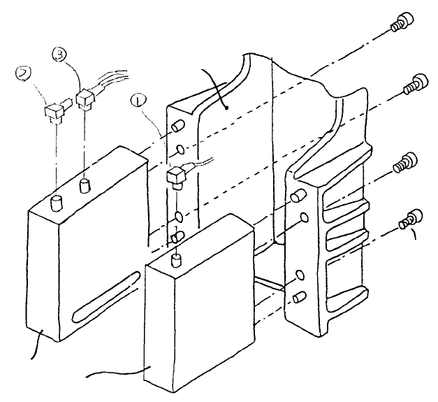
6-2 LA Sensor Replacement (LA, LAIC Head)
After replacement of LAHD, reentry of MS parameters for the laser is required. (Refer to section 2 - 13
for reentry.) After replacement, wipe the LAHD laser window with alcohol.
– To replace, remove connectors (1), (2) & (3) and the 4 screws (4).
SEMS cap scre
w
(SL6040842TN)
LA senso
r
Head bracket
Fig. 2-6-2
1-30
7. Head Up Spring Replacement
Remove head up spring (4) from spring stud (3) and replace. (Dia. 2 - 1 - 1~3)
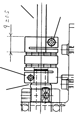
8. Coupling θ Replacement
(1) Loosen the 2 screws (1), (2) in coupling θ and remove coupling.
(2) To mount, insert coupling all the way onto Z slider shaft and secure with screw (1). Tighten screw
(2) to fix spline shaft so that the dimensions given below are achieved.
Spline shaft
Screw (2)
M3
Screw (1)
M2.5
Z slider shaft
Fig. 2-8-1
1-31
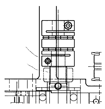
9. Coupling Z Replacement
Since Z-axis motor must be removed to replace coupling Z, afterwards, Z-axis home positioning must be
adjusted and Z-axis height and laser related MS parameters must be reentered. (Refer to section 2 - 13
for reentry.)
(1) Remove motor as directed in section 2 - 3.
(2) Loosen screw (1) and remove coupling.
(3) To mount, place coupling all the way onto ball screw and tighten screw.
(4) Mount motor as directed in section 2 - 3.
Ball scre
w
Scre
w
M2.5
Fig. 2-9-1
1-32