KE-750_MS.pdf - 第34页
5. Z-axis Deceleration Sensor Replacement Adjustment is not required after replacement of Z-ax is deceleration sensor, but be sure it is ON when Z-axis (Z slide bracket) is fully raised. (1) Disconnect the wire bundle of…
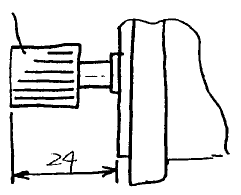
(5) When assembling θ-axis motor pulley, mount so that the distance from the θ-axis motor flange to the
θ motor pulley extremity is 24mm (Dia. 2 - 4 - 3).
(6) Reassemble in reverse sequence. Adjust timing belt θ tension. (Refer to QA Table, Head, θ belt
tension.)
θ motor pulley
Fig. 2-4-3
1-27
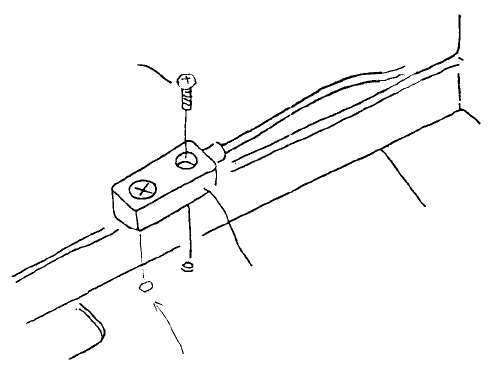
5. Z-axis Deceleration Sensor Replacement
Adjustment is not required after replacement of Z-axis deceleration sensor, but be sure it is ON when
Z-axis (Z slide bracket) is fully raised.
(1) Disconnect the wire bundle of the Z-axis deceleration sensor from head main PCB (at rear of head).
(2) Remove screw (1) and remove Z-axis deceleration sensor from head.
Note: Insert knob on the back of the
deceleration sensor into head bracket hole
to position.
Z-axis deceleration senso
r
Pot scre
w
(SM4860801SC)
Fig. 2-5-1
1-28
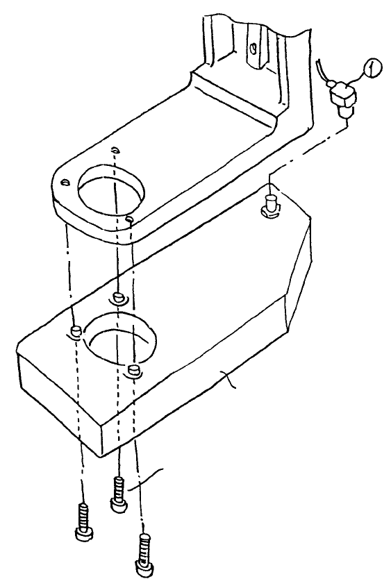
6. Laser Sensor Replacement
6-1 LAHD Replacement (LAHD Head)
After replacement of LAHD, reentry of MS parameters for the laser is required. (Refer to section 2 - 13
for reentry.) After replacement, wipe the LAHD laser window with alcohol.
– To replace, remove connector (1) and the 3 screws (2).
LAHD
A
llen head scre
w
(SM6852002TN)
Note: For the Allen head screws (2), use Locktite 242 and tighten to torque 4kg-cm.
Fig. 2-6-1
1-29