KE-750_MS.pdf - 第110页
10. Lock Up Valve Replacement (1) Remove accessory nut. (2) Slide lock up valve down from main body and remove. (3) Reassemble in reverse sequence. PJ301065201 Half union PJ305065201 Service union A ccessory nut E1619725…
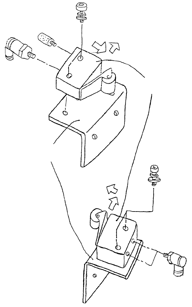
9. Roller Lever Replacement
(Optional One-Shot Replacement Base)
Carry out procedures after shutting off main air supply.
PJ304040505
Elbow union x 2
SL6042592TN
SEMS cap x 2
Roller leve
r
PV010505000
When fastening with M4
x 25, press roller lever in
direction of arrows and
fasten.
SL6042592TN
SEMS cap x 2
Right bank valve
assy
E2776721000
Bank valve plate
PJ304040505
Elbow union
PX050501000
Silencer
Left bank valve ass
y
Fig. 9-9-1
1-102
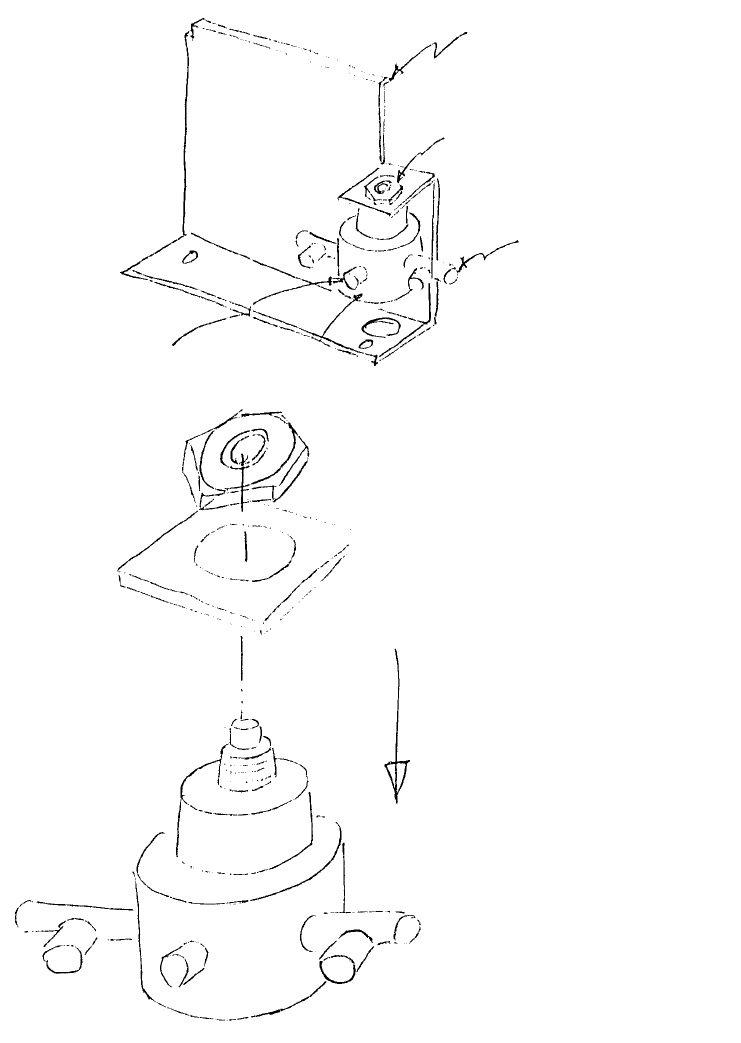
10. Lock Up Valve Replacement
(1) Remove accessory nut.
(2) Slide lock up valve down from main body and remove.
(3) Reassemble in reverse sequence.
PJ301065201
Half union
PJ305065201
Service union
A
ccessory nut
E1619725000
Feeder PWB bracket
1-103
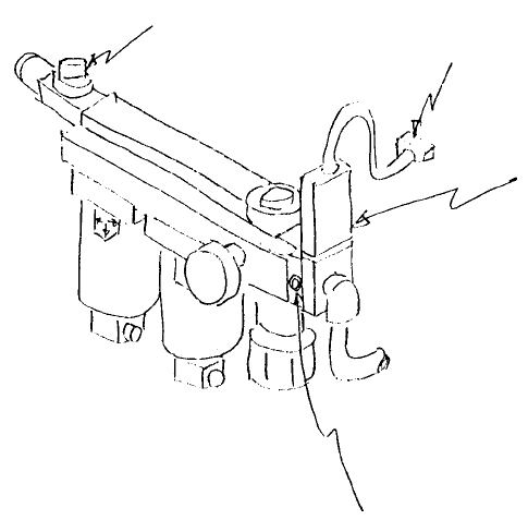
Chapter 10 Air Apparatus
1. Air Source Identification Cable Assy Replacement
(1) Unplug connector.
(2) Remove Allen head screw.
(3) Remove air source identification cable assy.
(4) Reassemble in reverse sequence.
Caution
– Shut hand valve before beginning.
– Refer to relevant Users' Manual for method of adjusting pressure switch.
A
llen head scre
w
E94037250A0
A
ir source identification cable
assy (Pressure switch)
Connecto
r
Hand valve
Fig. 10-1-1
1-104