KE-750_MS.pdf - 第42页
13. Summary of Readjustments Required after Replacement - Enter MS parameters in the order given above star ting at the top. (Refer to MS parameter control specifications.) Head unit assy Z slider shaft assy Z-axis motor…
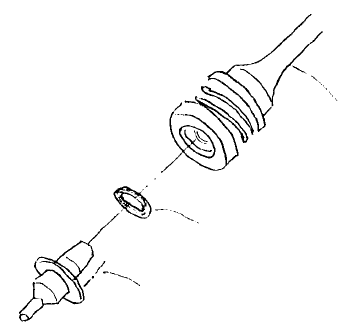
12. O-Ring Replacement
(1) Use a pincet or similar tool to remove O-ring from inside Z slider shaft taking care not to damage the
inside of the shaft.
(2) Insert new O-ring snugly into the shaft.
(3) After replacement, lightly coat the contact surface of the nozzle to the O-ring with grease and
join/separate with shaft several times to coat O-ring.
Greased surface
O-ring
Z slider shaft
Fig. 2-12-1
1-35

13. Summary of Readjustments Required after Replacement
- Enter MS parameters in the order given above starting at the top. (Refer to MS parameter control
specifications.)
Head unit
assy
Z slider
shaft assy
Z-axis
motor assy
θ-axis
motor assy
Laser
sensor
Coupling
Z
Spline housing
assy
Head centering
{
Z-axis home adjust
{
{
θ belt tension adjust
{
{
Laser offset
{ { {
{ {
Laser scaling
{ {
{
VCS camera offset
VCS general offset*
{ {
ATC
Nozzle Setup
{ {
{
Vacum value
without Nozzle
{ {
Head offset
{ {
{
(*) Note: Only applies to LAIC head.
1-36
Chapter 3 Head Periphery
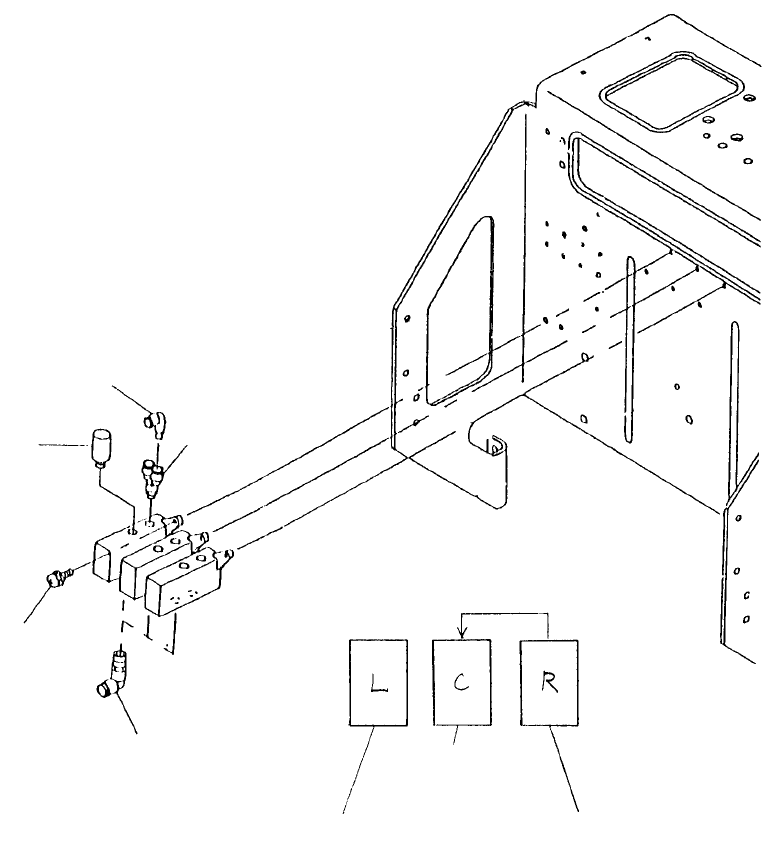
1. Vacuum Switch Solenoid Replacement
As the vacuum switching solenoid continuously supplies the main body from the pressure source,
replace after main body pressure has fallen.
Note: For model 760 use a right head solenoid in the
center solenoid position.
Head 2 vacuum
ON cable assy
E93177250A0
Head 1 vacuum
ON cable assy
E93147250S0
Head 3 vacuum
ON cable assy
E93207250A0
Note: Only for model 760
Elbow union
PJ304040505
SEMS scre
w
SL4030881SL
Branch
PJ308065101
Silence
r
PX058001000
Reducer elbo
w
PJ304040004
Fig. 3-1-1
1-37