KE-750_MS.pdf - 第236页
4.15 ATC Offset Select "2/Offset set-up" then "7/A TC Offset", and the ATC offset setting dialog will appear as follows. (KE-760) (KE-750) (1) Setting Items No. Item Contents 1 Assembling Position Off…

Overview of Error Codes (1/2)
Error Code Meaning Cause How to Restore
0x00 Comment
0x01 Sequence error Error in command transmission
sequence
Use correct command sequence
0x02 Insufficient data Required data missing Use correct data
0x03 Parameter error Received invalid command Use correct parameter values
0x04 Improper command Improper command Use correct command
0x05 Incorrect Data Data exceeds limits Check system setup
0x06 Nonconforming
Template
Parts template and lead numbers not
aligned
Check if all leads are running through
focus
0x07 Function Invalid Command sent is invalid in system Use command valid for system
0x08 Insufficient Template
Memory
Capacity of template library exceeded Shrink template size in library
0x09 Incorrect String Non-numeric parameters sent with
command
Only transmit numeric commands
0x10 UART Receive Overrun
Error
0x11 UART Parity Error
0x12 UART Framing Error
0x20 Sensor 0 EEPROM
Read Error
Transmission trouble with L3 sensor 0 Check cable connecting L3 PWB and
L3 sensor 0. Reset software
0x21 Sensor 1 EEPROM
Read Error
Transmission trouble with L3 sensor 1 Check cable connecting L3 PWB and
L3 sensor 1. Reset software
0x22 Sensor 0 Simultaneous
Error
Transmission trouble with L3 sensor 0 Check cable connecting L3 PWB and
L3 sensor 0. Reset software
0x23 Sensor 1 Simultaneous
Error
Transmission trouble with L3 sensor 1 Check cable connecting L3 PWB and
L3 sensor 1. Reset software
0x40 Beam Obstruction Error Unnatural position of entering beam Check that beam is not obstructed.
Try resetting software.
0x41 Beam Entry Error Unnatural obstruction of entering
beam
Check that beam is not obstructed.
Try resetting software.
0x42 Sensor DAC Error Beam to photodictor excessive or
laser threshold judged unusually high
due to hardware malfunction
Contact CyberOptics Co.
0x43 NPX Error Control hardware malfunction Contact CyberOptics Co.
Note: Contents of error code are only valid when status error byte (byte 2) is "1". An error byte
setting of "0" carries no meaning.
2-68
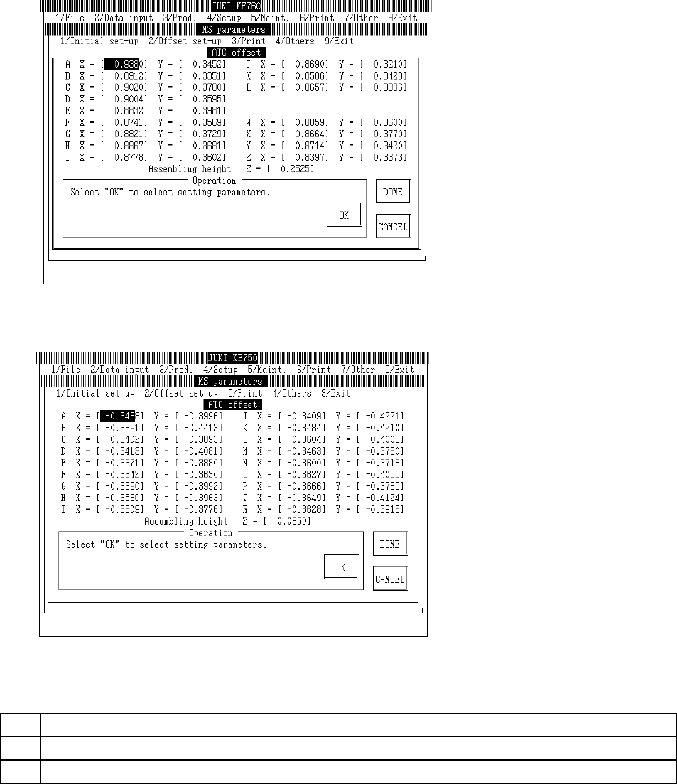
4.15 ATC Offset
Select "2/Offset set-up" then "7/ATC Offset", and the ATC offset setting dialog will appear as follows.
(KE-760)
(KE-750)
(1) Setting Items
No.
Item Contents
1 Assembling Position Offset value from the setting position of each ATC nozzle housing hole
2 Assembling Angle Offset value from the Z direction setting position of the ATC
2-69
(2) Method of Setting
– Enter values directly with the keyboard or follow the internal operating instructions for
automatic input.
– When entering assembling position with teaching, values are simultaneously modified when
input focus meets the assembling position of either X or Y.
– When entering assembling position with teaching, first set ATC offset poss in the
corresponding cylinder before proceeding.
– When entering assembling position with teaching, input focus must be at assembling height.
– Select HOD device key to enter teaching.
– If head is in the way, move with control menu.
– Relevant functions
F7 key: Saves Y axis coordinates and moves X axis to A position of ATC.
F8 key: Saves Y axis coordinates and moves X axis to final position (KE-740 & KE-760:
Z of ATC; KE-730 & KE-750: R of ATC).
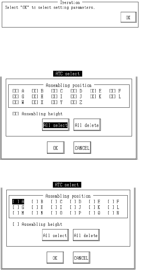
– Operating method of automatic input
(1) Assembling Position
Once completed, select "OK".
When "OK" is selected, dialog for selecting setting parameter appears.
KE760
KE750
2-70