KE-750_MS.pdf - 第154页
11-2 Method of Mounting ARCNET PWB (1) Remove the 4 screws in the enlarged slot box. (2) Disconnect enlarged slot box fr om main PWB (DIN connector). (3) Attach ACRNET PWB with stop screw to connector CN4 of the removed …
11. Panel Computer Set-up
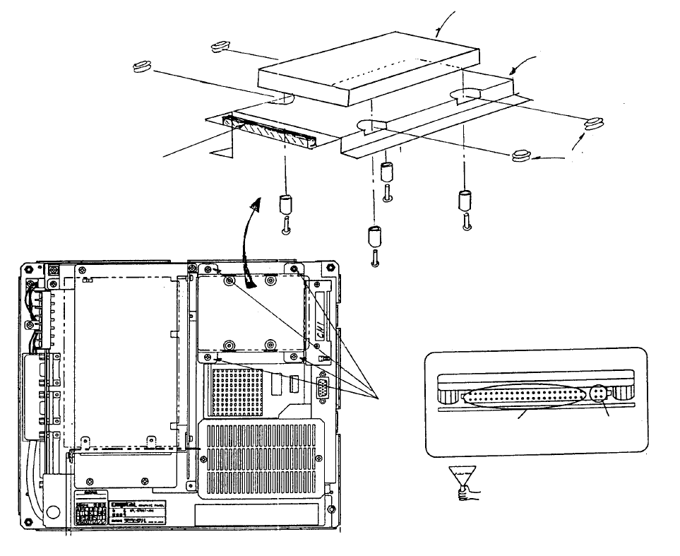
11.1 Method of Mounting Hard Disk
(1) Remove flat cable connector from CN1 of Mother 2 PWB.
(2) Remove 4 sheet metal screws from hard disk mounting plate.
(3) Insert rubber bushes into hard disk mounting plate.
(4) Place hard disk onto hard disk mounting plate.
(5) Fasten with the screws for the hard disk.
(6) Plug in flat cable connector to CN1 of Mother 2 PWB.
(7) Plug flat cable connector into hard disk.
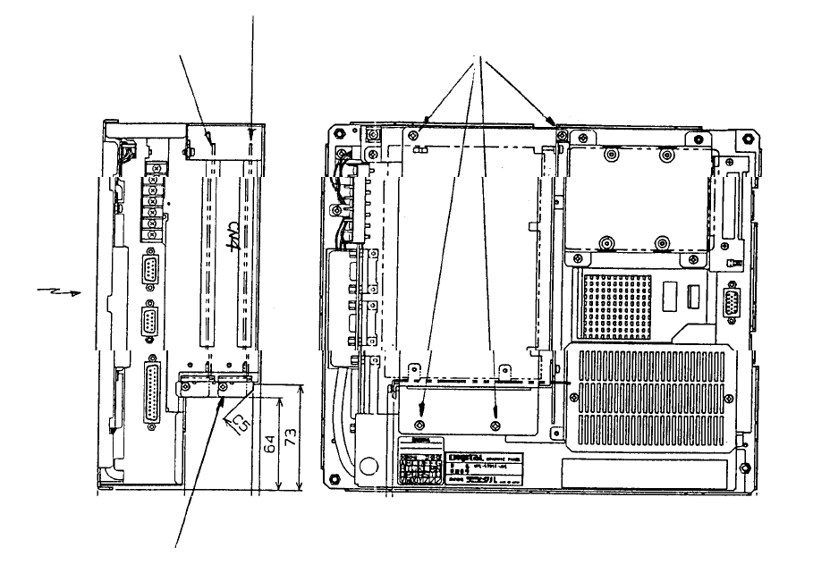
(8) Screw hard disk mounting plate onto main body.
HDD Connector Front
Di
These 4 pins
are not used.
Cable is
plugged in here.
(Bottom)
View of back face of panel compute
r
Scre
w
(1) x 4
Mounting
plate
(Top)
Mother 2 board
Note: Screws, round column
spacers and rubber bushes are
accessories to panel computer.
Screw x 4
Spacer x 4
Caution: Imprope
r
connection may lead to
damage of the equipment
when power is supplied.
Rubber bush x 4
Panel compute
r
(Top)
Mounting plate
HDD (Hard disk drive) E9613721000
Panel computer (Bottom)
1-138
11-2 Method of Mounting ARCNET PWB
(1) Remove the 4 screws in the enlarged slot box.
(2) Disconnect enlarged slot box from main PWB (DIN connector).
(3) Attach ACRNET PWB with stop screw to connector CN4 of the removed enlarged slot box.
(4) Reconnect enlarged slot box to main PWB of main body(DIN connector).
(5) Tighten screws holding enlarged slot box to main body.
Panel computerBac
k
Position of PWB stop
screws
Front right
side
LCD
(Front)
(Bottom)
Enlarged
slot box
HDD
(Top)
Screw x 4
Mount ARCNET PWB
(E86117250A0)
Optional: Mount
A
RCNET PWB HLC
1-139
11-3 Hard Disk Format
11-3-1 Format Sequence
1. Setting BIOS
Sets report of peripheral equipment (HDD, FDD, etc.) to panel computer memory.
(1) Connect keyboard and FDD (floppy disk drive) to panel computer.
(2) Supply power to panel computer.
(3) On screen A "Press <F2> to Enter SETUP" will appear. Press [F2] key and hold down.
(4) Once set up utility is activated, BIOS screen will appear.
(5) Look over the overview of key controls at the bottom of the screen. Move the cursor to
check each item do setup.
1 System time: [Hr:Min:Sec] Enter time.
2 System date: [Mo/Day/Yr] Enter today's date.
3 Diskette A: 1.44MB, 31/2"
4 Diskette B: Set to Not Installed.
5 IDE Adapter 0 Master (None) Press ENTER key and screen B will display.
Autotype Fixed Disk: Press ENTER key and HDD type is automatically set.
(Ex: 541MByte)
6 Video System: Select EGA / VGA.
7 Memory Cache: Do not alter.
8 Memory shadow: Do not alter.
9 Boot Sequence: Select A: then C: (*) Note
10 Press ESCAPE key. Move cursor to EXIT at top of screen A.
11 Screen C will display.
Select "Save Changes & Exit" to store set values in CMOS.
NO System and ERROR messages that appear may be ignored. These are not set in the
MS-DOS installed disk of the FDD.
(*) Note: After format operation 17 - 11 - 3 - 2, message will revert to "C: then A: ".
1-140