KE-750_MS.pdf - 第230页
– Operating method of automatic input Follow instructions to operate and values will automatically acquire. Set #203 nozzle in LAIC head. Once completed, select "OK". When "OK" is selected, nozzle mov…
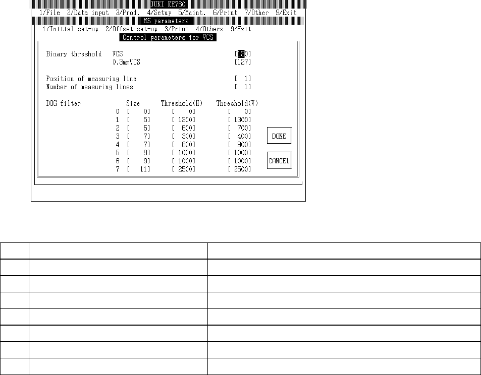
4.13.5 VCS Common Parameters
Select "2/Offset set-up" then "5/VCS", "7/Control parameters for VCS" and the VCS common
parameter setting dialog will appear as follows.
(1) Setting Items
No. Item Contents
1 Binary Threshold Value Std VCS Standard VCS binary threshold value
2 Binary Threshold Value 0.3mm VCS 0.3mm VCS binary threshold value
3 Position of Measuring Lines Position of measuring lines
4 No. of Measuring Lines Number of measuring lines
5 DOG Filter Size Size of DOG filter
6 DOG Filter Threshold Value (Side) Filter threshold value in side direction
7 DOG Filter Threshold Value (Length) Filter threshold value in length direction
(2) Method of Setting
– Input values directly from keyboard.
– There are 16 types of DOG filter (0~15) for component form recognition. The input field is
divided 0~7 and 8~15. Use "Pg Up" and "Pg Dn" keys to move between fields.
– When F10 key is pressed, binary threshold values are automatically entered.
– Focus position when F10 key is selected distiguishes setting VCS.
Standard VCS is set to focus binary threshold values in standard VCS.
0.3mm VCS is set to focus binary threshold values in standard 0.3mm VCS.
2-62
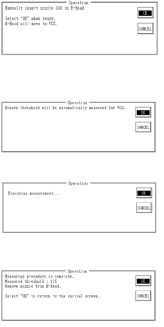
– Operating method of automatic input
Follow instructions to operate and values will automatically acquire.
Set #203 nozzle in LAIC head.
Once completed, select "OK".
When "OK" is selected, nozzle moves to setting VCS.
– Contents of Measurement
(1) The binary threshold value is automatically measured with nozzle.
Once measurement is completed, result is displayed.
Remove #203 nozzle from LAIC head.
Once completed, select "OK" or "Cancel".
When "OK" is selected, the binary threshold values of setting VCS are modified and operating
screen clears.
When "Cancel" is selected, the binary threshold values of setting VCS are not modified and
operating screen clears.
2-63
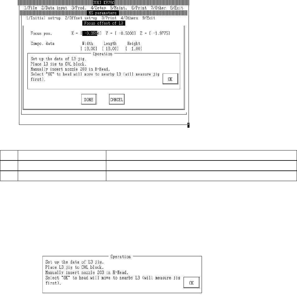
4.14 Coplanarity Offset
4.14.1 L3 Focus Offset
Select "2/Offset set-up" then "6/Coplanarity", "1/Focus Offset of L3" and the L3 focus offset dialog
will appear as follows.
(1) Setting Items
No. Item Contents
1 Focus Position Offset value from L3 sensor focus set position
2 Parts Data L3 jig parts data for focus offset measurement (temporary parameter)
(2) Method of Setting
– Enter values directly with the keyboard or follow the internal operating instructions for
automatic input.
– Select HOD device key to enter teaching.
– Operating method of automatic input
Follow instructions to operate and values will automatically acquire.
Input L3 jig data.
Place L3 jig on top of CAL block.
When jig suction is turned on, OCC recognizes L3 jig position. L3 jig is placed onto CAL block so
that its 2 holes see the CAL block illumination.
Manually set #203 nozzle in LAIC head.
When "OK" is selected, LAIC head suction takes L3 jig and laser recognizes L3 jig.
When recognition of L3 jig is completed, head moves to a spot nearby (parking point). Displace
of L3 is automatically corrected based on the recognition result.
2-64