KE-750_MS.pdf - 第96页
Chapter 9 Feeder Bank One-Shot Replacement (Optional) (1) Air tube (2) Connector (2) Connector (1) Air tube Drive cylinder 20 Left E26317210A0 Bank lifter / Lef t E2754721000 Driver bracke t E2633721000 Head Driver brack…
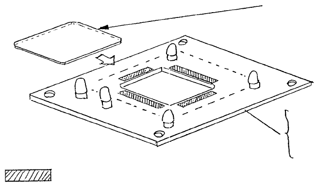
(2) Cover glass replacement
a. Refer to section 10 - 3 and remove VCS light PWB assy.
b. Transfer cover glass to the new PWB.
c. Fasten PWB.
Note: 1. Double-sided tape must not protrude into opening.
2. Do not leave fingerprints etc., on glass.
Clean areas to
r
emove grease and attach cove
r
glass with double-sided tape.
E86157210A0
0.4 VCS light PWB assy
E86527210A0
0.3 VCS LIGHT PWB assy
E3704721000
Cover glass
Fig. 8-4-2
1-88
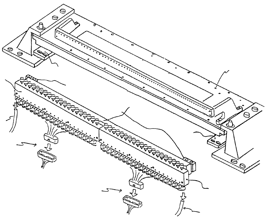
Chapter 9 Feeder Bank One-Shot Replacement (Optional)
(1) Air tube
(2) Connector
(2) Connector
(1) Air tube
Drive cylinder 20 Left
E26317210A0
Bank lifter
/
Lef
t
E2754721000
Driver bracke
t
E2633721000
Head
Driver bracke
t
support
Bank lifter / Right
E2755721000
Drive cylinder 20 Right
E26327210A0
Fig. 9-1-1
Driver bracket support A - Standard
E2634721000
Driver bracket support B - Optional (One-shot replacement base)
E2791721000
1-89
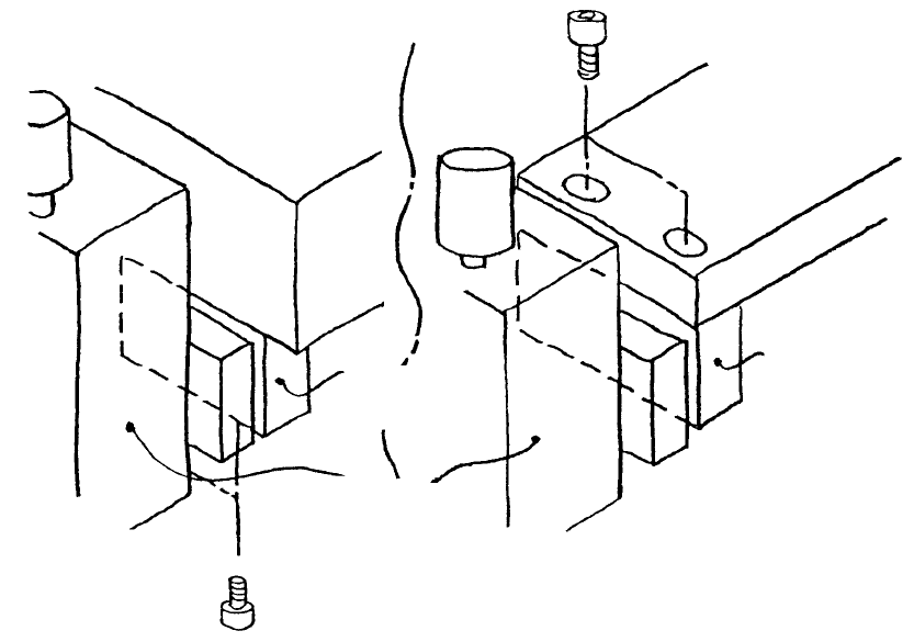
1. Drive Cylinder Replacement (Refer to Dia. 9 - 1 - 1)
(1) Turn main power source OFF.
(2) Shut off main air supply (hand valve).
(If the optional one-shot replacement base is used, disconnect and remove it from the main body.
Turn sensor and left / right roller lever ON. Raise bank lifter and shut off air.)
(3) Disconnect left / right air tubes (1) and connectors (2).
(4) Remove screws holding driver bracket support.
– For standard layout, driver bracket support A is attached through the bottom to the bottom of the
bank.
– For the one-shot replacement base, the driver bracket support B is attached through the top of
the bank lifter.
Driver bracket
support B
Drive cylinde
r
Driver bracket
support A
Bank lifte
r
Ban
k
(Standard) (One-shot replacement base)
Fig. 9-1-2
1-90