KE-750_MS.pdf - 第99页
2. Drive Cy linder Solenoid Valve Replacement (1) Press at point indicated by arrow and pull down to remove cable. (2) Remove the 2 screws holding solenoid and remove solenoid. (3) Mount new solenoid valve. (4) Insert ca…
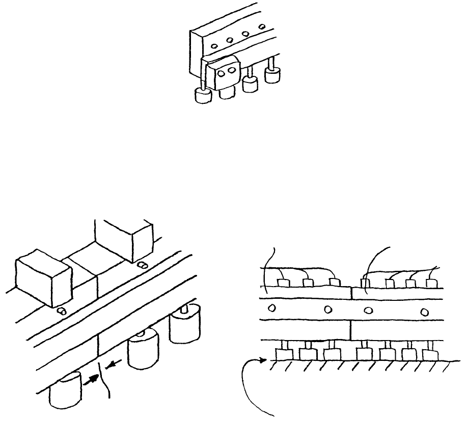
(5) Replace with new drive cylinder oriented upside-down as in Dia. 9 - 1 - 3.
Note: Work from the even surface of the table or the top of the bank.
– Mount so there is no gap between left & right cylinders (Dia. 9 - 1 - 3, Dia. 9 - 1 - 4).
– Mount so there is minimal gap between bank top surface and up/down cylinders (Dia. 9 - 1 - 5).
Fig. 9-1-3
Only replace left & right cylinders one at a time.
Previously mounted
cylinder
Bank top surface
No gap
No gap
Replaced cylinde
r
Fig. 9-1-4 Fig. 9-1-5
(6) Reassemble in reverse sequence.
1-91
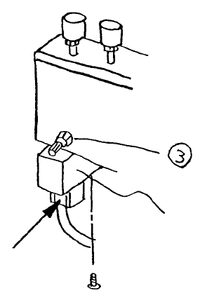
2. Drive Cylinder Solenoid Valve Replacement
(1) Press at point indicated by arrow and pull down to remove cable.
(2) Remove the 2 screws holding solenoid and remove solenoid.
(3) Mount new solenoid valve.
(4) Insert cable and press firmly until it clicks.
Solenoid valve
Fig. 9-2-1
1-92
3. Drive Cylinder Speed Control Adjustment
For adjustment of up/down speed of numerous cylinders
(1) Disconnect drive cylinders needing adjustment from driver bracket.
(Refer to 9 - 1 - (1)~(4).)
(2) Connect air tube (1) with connector (2).
(3) Turn on mains air and power.
(4) Using In/Out manual control, continuously all drive cylinders of the speed controller to be regulated.
(5) Regulate the cylinders with the speed controller. Judge by eye that movement is the same as the
other cylinders. (Refer to Dia. 9 - 2 - 1.)
(6) After tightening speed controller nut to secure setting, verify movement one more time.
(7) Reassemble in reverse sequence.
1-93