Forte Max Manual.pdf - 第15页
ForteMAXDispensingSystemAddendum Installation an d Setup © 2023 Nordson Corporation 11 3.4 Designing the Disp ense Layout Prior to setting up the system hardware, you must design the board layout. The slide bracket p…
10 © 2023 Nordson Corporation
3 Installation and Setup
3.1 Overview
This section covers hardware and software setup and calibration for both dual-simultaneous and
dual-action dispensing. This section covers the following topics:
• Designing the Dispense Layout
• Slide Bracket Positions
• Installing the Slide Bracket
• Dry Valve Offsets Procedure
3.2 Safety First
Operation of the dispensing system involves heat, air pressure, electrical power, mechanical devices, and
the use of hazardous materials. It is essential that every person servicing or operating the dispensing
system fully understands all hazards, risks, and safety precautions. Refer to Section 2 – Safety in this
manual and to the Forte Dispensing System Installation, Operations, and Maintenance Manual for
important safety information.
WARNING!
Allow only qualified personnel to perform the following tasks. Follow the safety
instructions in this document and all other related documentation.
3.3 Tools and Materials Needed:
•
R
u
l
e
r
•
S
t
a
n
d
a
r
d
S
l
i
d
e
B
r
a
c
k
e
t
(
Item
2
21
)
•
C
a
l
i
p
e
r
•
H
e
x
W
r
e
n
c
h
e
s
(
2
.
5
m
m
,
3
m
m
,
4
.
5
m
m
)
•
T
o
r
q
u
e
W
r
e
n
c
h
(
0
-
1
0
0
i
n
l
b
s
)
ForteMAXDispensingSystemAddendum Installation and Setup
© 2023 Nordson Corporation 11
3.4 Designing the Dispense Layout
Prior to setting up the system hardware, you must design the board layout. The slide bracket position
depends on the board layout. Select a board that is as close to perfect as possible when teaching the
board for the first time. This allows the largest room for valve adjustment on a board with a rotated part. If
you start with a board with rotated parts, you may not have the room to adjust.
Select the layout design solution that has the shortest valve pitch within the range of 45 mm to 112 mm.
The longer the distance between Valve 1 (V1) and Valve 2 (V2), the less accurate the dispensing results
and the shorter the X travel (Figure 3-3 and Figure 3-4).
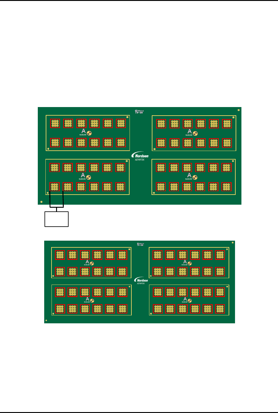
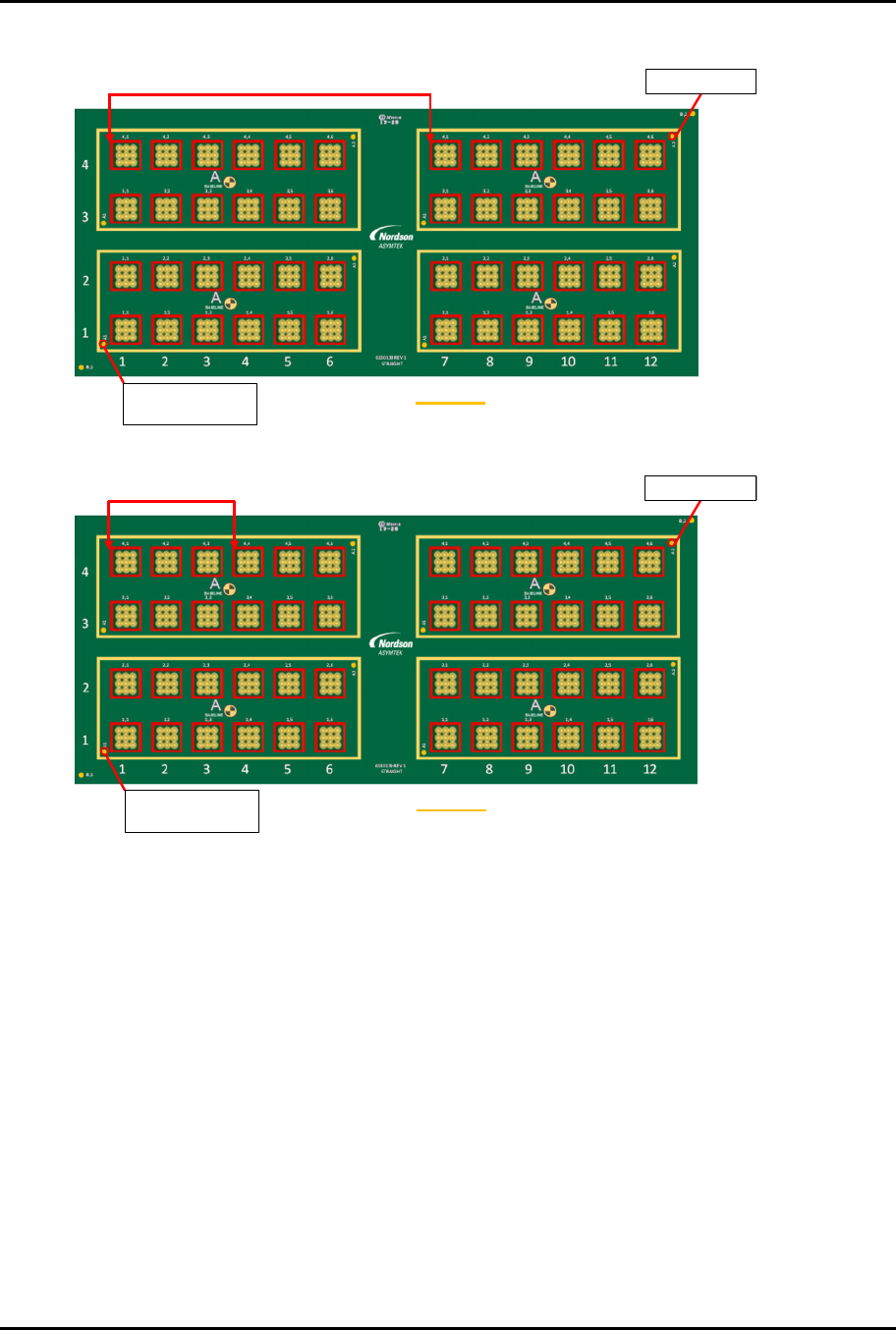
The following multi-up panel board (Figure 3-1) is used as an example for both the dual simultaneous and
dual-action recipes detailed in this manual. The pitch between the parts to be dispensed on (part pitch)
is 16.5 mm.
4,1 4,2 4,3 4,4 4,5 4,6
A2
A1
3,1 3,2 3,3 3,4 3,5 3,6
1 2 3 4 5 6 7 8 9 10 11 12
4
3
2
1
2,1 2,2 2,3 2,4 2,5 2,6
A2
A1
1,1 1,2 1,3 1,4 1,5 1,6
4,1 4,2 4,3 4,4 4,5 4,6
A2
A1
3,1 3,2 3,3 3,4 3,5 3,6
2,1 2,2 2,3 2,4 2,5 2,6
A2
A1
1,1 1,2 1,3 1,4 1,5 1,6
6130139 R EV 1
STRAIGHT
B,1
B,2
Part Pitch
16.5 mm
The application requirement (dispense on all the red squares) is shown in Figure 3-2.
1 2 3 4 5 6 7 8 9 10 11 12
4
3
2
1
6130139 REV 1
STRAIGHT
B,1
B,2
2,1 2,2 2,3 2,4 2 ,5 2,6
1,1 1,2 1,3 1,4 1,5 1,6
4,1 4,2 4,3 4,4 4,5 4,6
A2
A1
3,1 3,2 3,3 3,4 3,5 3,6
A2
A1
4,1 4,2 4,3 4,4 4,5 4,6
A2
A1
3,1 3,2 3,3 3,4 3,5 3,6
A2
A1
2,1 2,2 2,3 2,4 2,5 2,6
1,1 1,2 1,3 1,4 1,5 1,6
Figure 3-2 Application Requirement
F
ig
u
re
3
-
1
M
u
l
t
i
-
U
p
P
a
n
e
l
ForteMAXDispensingSystemAddendum Installation and Setup
12 © 2023 Nordson Corporation
There are two possible layout options (Figure 3-3 and Figure 3-4).
V1
V1 V2
V2
Workpiece Origin
and Workpiece Fid 1
Workpiece Fid 2
Container
Figure 3-3 Layout Option 1
V1
V1 V2
V2
V1
V1 V2
V2
Workpiece Fid 2
Workpiece Origin
and Workpiece Fid 1
Container
Figure 3-4 Layout Option 2
Option 2 is the best option, since the valve pitch for Option 1 is 121.5 mm, which is larger than the
allowable valve pitch range of 45 mm to 112 mm listed in Table 3-1.