Forte Max Manual.pdf - 第59页
ForteMAXDispensingSystemAddendum Maintenance © 2023 Nordson Corporation 55 7. Note the slide bracket posit ion. 8. Remove the four ( 4 ) scre ws securing the slide bracket to the dispense head (Figure 5-2). 9. Remove…
ForteMAXDispensingSystemAddendum Maintenance
54 © 2023 Nordson Corporation
5.3 Lubricating the Forte MAX Bracket
The Forte MAX bracket should be lubricated every six (6) months.
Tools and Materials Needed:
• Forte MAX Grease Kit (Item 181)*
• Torque Wrench 1.3 Nm (12 in-lbs) (Customer Supplied)
*The Forte Max Grease Kit contains the following grease: ISOFLEX, TOPAS NCA 52, MICROLUBE GL 262, and Super Lube
Synthetic Grease with PTFE
WARNING!
Refer to the applicable SDS for important safety information pertaining to the
greases used in this procedure.
To lubricate the Forte MAX bracket:
1. Lower the Delta Z all the way down in the Canvas dispensing software.
2. Close the Canvas dispensing software.
3. Perform a service shutdown, see 2.11 Service Shutdown.
WARNING!
Failure to shut down the power and pneumatic pressure can result in severe injury
to personnel or damage to the dispensing system.
4. Open the dispensing system hatch and remove both valves. Refer to the applicable valve
manual for removal.
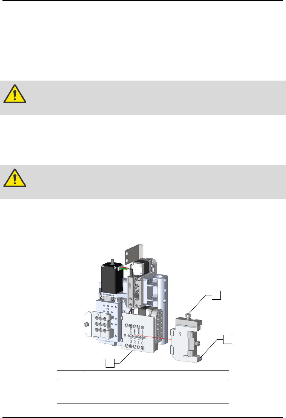
5. Loosen the dovetail mounting screw (Figure 5-1).
6. Remove the right dovetail assembly by sliding it to the right.
Item
Desc
riptio
n
1 Dovetail Mounting Screw
2 Right Dovetail Assembly
3 Standard Slide Bracket
Figure 5-1 Removing the Right Dovetail
1
2
3
ForteMAXDispensingSystemAddendum Maintenance
© 2023 Nordson Corporation 55
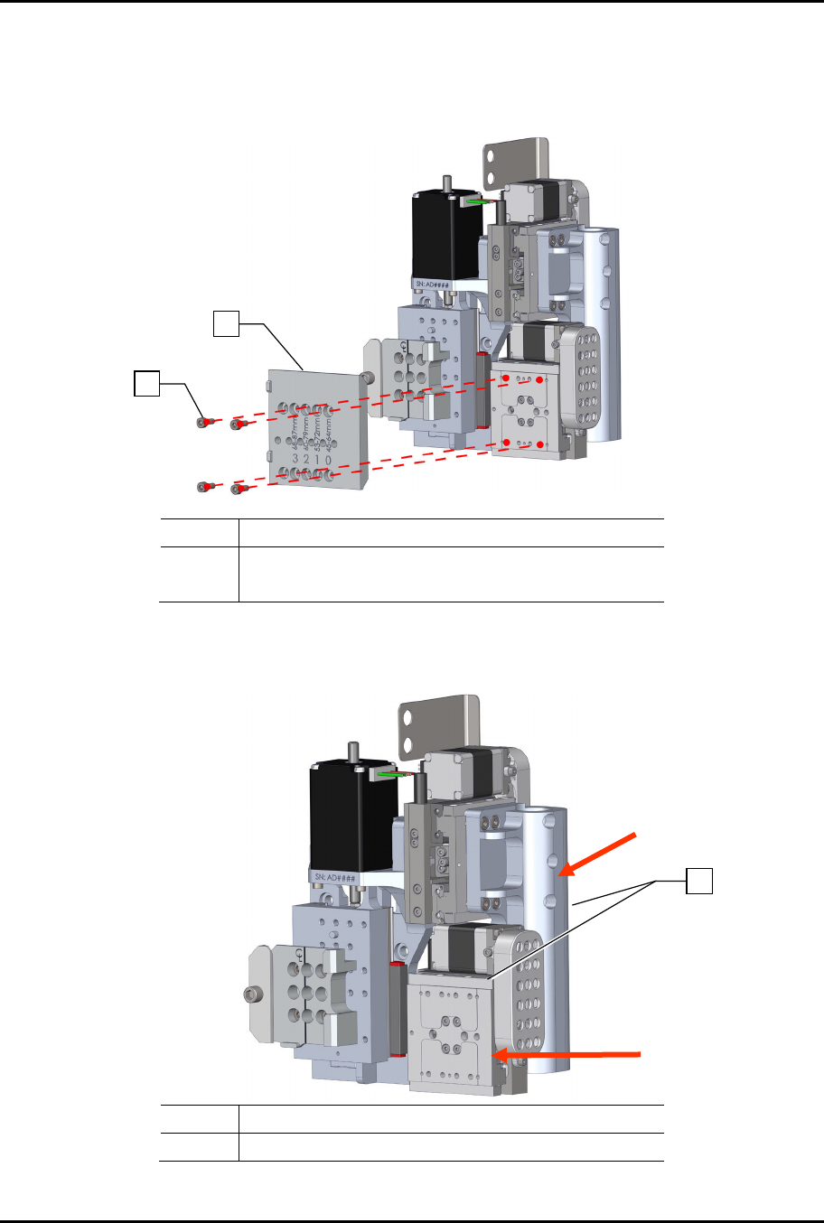
7. Note the slide bracket position.
8. Remove the four (4) screws securing the slide bracket to the dispense head (Figure 5-2).
9. Remove the slide bracket.
Item Description
1 Screws
2 Slide Bracket
Figure 5-2 Removing the Slide Bracket
10. Manually move the Delta XY motors for Valve 2 forward and to the left (Figure 5-3).
Item Description
1 Valve 2 Delta XY Motors
Figure 5-3 Move Valve 2 Delta XY Motors Forward and to the Left
1
2
1
ForteMAXDispensingSystemAddendum Maintenance
56 © 2023 Nordson Corporation
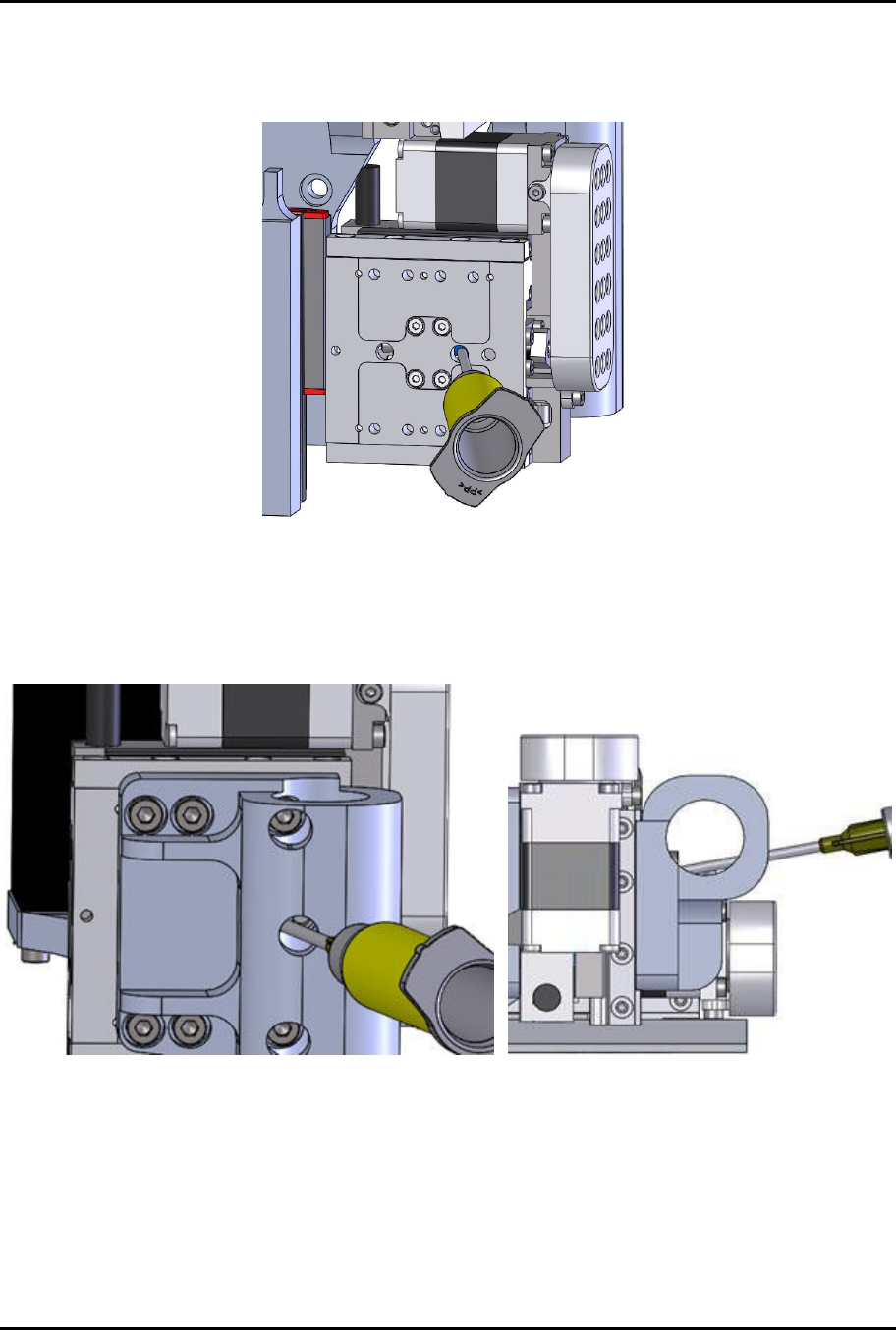
11. Grease the right X ball screw by inserting the syringe through the hole and injecting a small
amount of ISOFLEX TOPAS NCA-52 grease (Figure 5-4).
> The X ball screw is shown in blue.
Figure 5-4 Right X Ball Screw Grease Location
12. Grease the Y ball screw by inserting the syringe through the hole at an angle and injecting a
small amount of ISOFLEX TOPAS NCA-52 grease (Figure 5-5).
> The X ball screw is shown in blue.
Figure 5-5 Y Ball Screw Grease Location