Forte Max Manual.pdf - 第22页
ForteMAXDispensingSystemAddendum Installation an d Setup 18 © 2023 Nordson Corpo ration 11. Install the slide bracket in the desired position and loosel y tighten the screws (Figure 3-11). > The standard slide bra…
ForteMAXDispensingSystemAddendum Installation and Setup
© 2023 Nordson Corporation 17
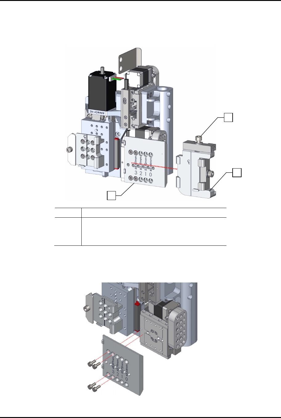
9. If the right dovetail is attached, loosen the dovetail mounting screw and slide the dovetail
assembly to the right (Figure 3-9).
> The slide bracket in Figure 3-9 is shown in Position 3 as indicated by the position of the
lower right screw below #3 on the slide bracket.
Item Description
1 Dovetail Mounting Screw
2 Right Dovetail Assembly
3 Standard Slide Bracket
Figure 3-9 Removing the Right Dovetail
10. Remove the four (4) screws securing the slide bracket to the dispense head and adjust the
bracket position as necessary (Figure 3-10).
Figure 3-10 Remove Slide Bracket Mounting Screws
1
2
3
ForteMAXDispensingSystemAddendum Installation and Setup
18 © 2023 Nordson Corporation
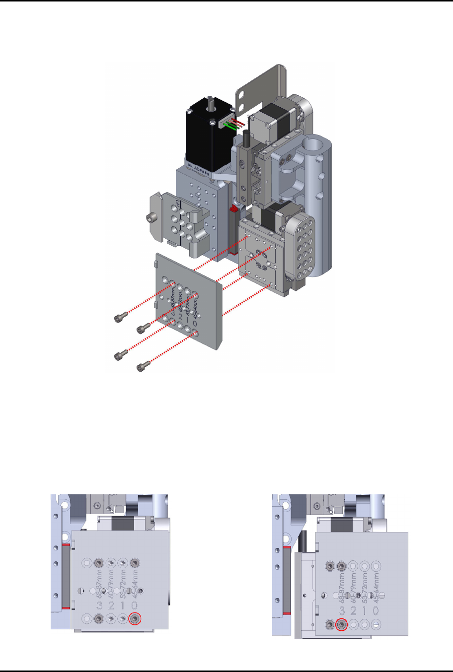
11. Install the slide bracket in the desired position and loosely tighten the screws (Figure 3-11).
> The standard slide bracket will be installed in Position 0 because the valve pitch is
50 mm (Table 3-1).
Figure 3-11 Installing the Slide Bracket
12. While applying a slight downward pressure on the slide bracket so that it is resting, and in
alignment with the alignment length in the back, torque the four (4) screws to 1.3 Nm
(12 in-lbs).
> Figure 3-12 and Figure 3-13 show the slide bracket in Position 0 and Position 3.
> As stated in 3.5 Slide Bracket Positions, the slide bracket position depends on the valve
pitch range (
Figure 3-3 and Figure 3-4).
Figure
3
-
12
S
l
i
d
e
B
r
a
c
k
e
t
i
n
P
o
s
i
t
i
o
n
0
Fi
g
ure
3
-
13
S
l
i
d
e
B
r
a
c
k
e
t
i
n
P
o
s
i
t
i
o
n
3
ForteMAXDispensingSystemAddendum Installation and Setup
© 2023 Nordson Corporation 19
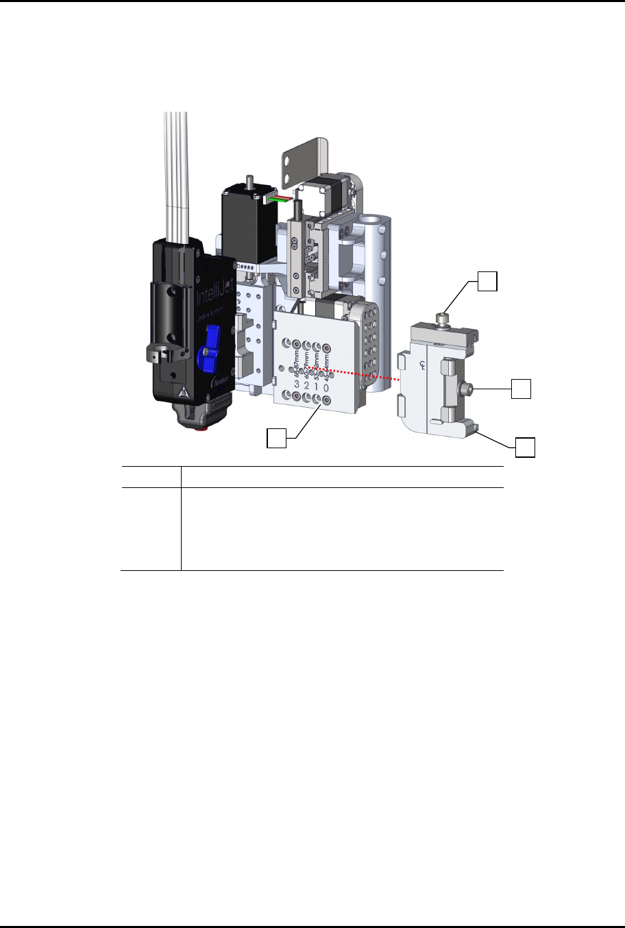
13. Replace the right dovetail assembly and loosely tighten the dovetail mounting screw
(Figure 3-14).
> Do not tighten the dovetail mounting screw all the way. The mounting screw will be
tightened after both valves have been installed and the distance between the valves
has been verified.
Item Description
1 Dovetail Mounting Screw
2 Dovetail Side Screw
3 Right Dovetail Assembly
4 Standard Slide Bracket
Figure 3-14 Installing the Right Dovetail Assembly
14. Adjust the conveyor width to accommodate the board size.
15. Adjust the lift tables and clamps so that the board does not move during programming.
16. Go to Step 8 to Home the Forte MAX bracket.
17. Install Valve 1 into the Valve 1 dovetail bracket.
18. Install Valve 2 into the Valve 2 dovetail bracket and tighten the dovetail side screw to
secure the valve (Figure 3-14).
> The dovetail mounting screw (top screw) should be loose so the dovetail can be moved
for final pitch adjustment.
4
3
1
2