Forte Max Manual.pdf - 第66页
ForteMAXDispensingSystemAddendum Maintenance 62 © 2023 Nordson Corpo ration 21. Loosely install the slide bracket in the po sition noted during removal. > Th e f our (4) screws should be loose. 22. While applying …
ForteMAXDispensingSystemAddendum Maintenance
© 2023 Nordson Corporation 61
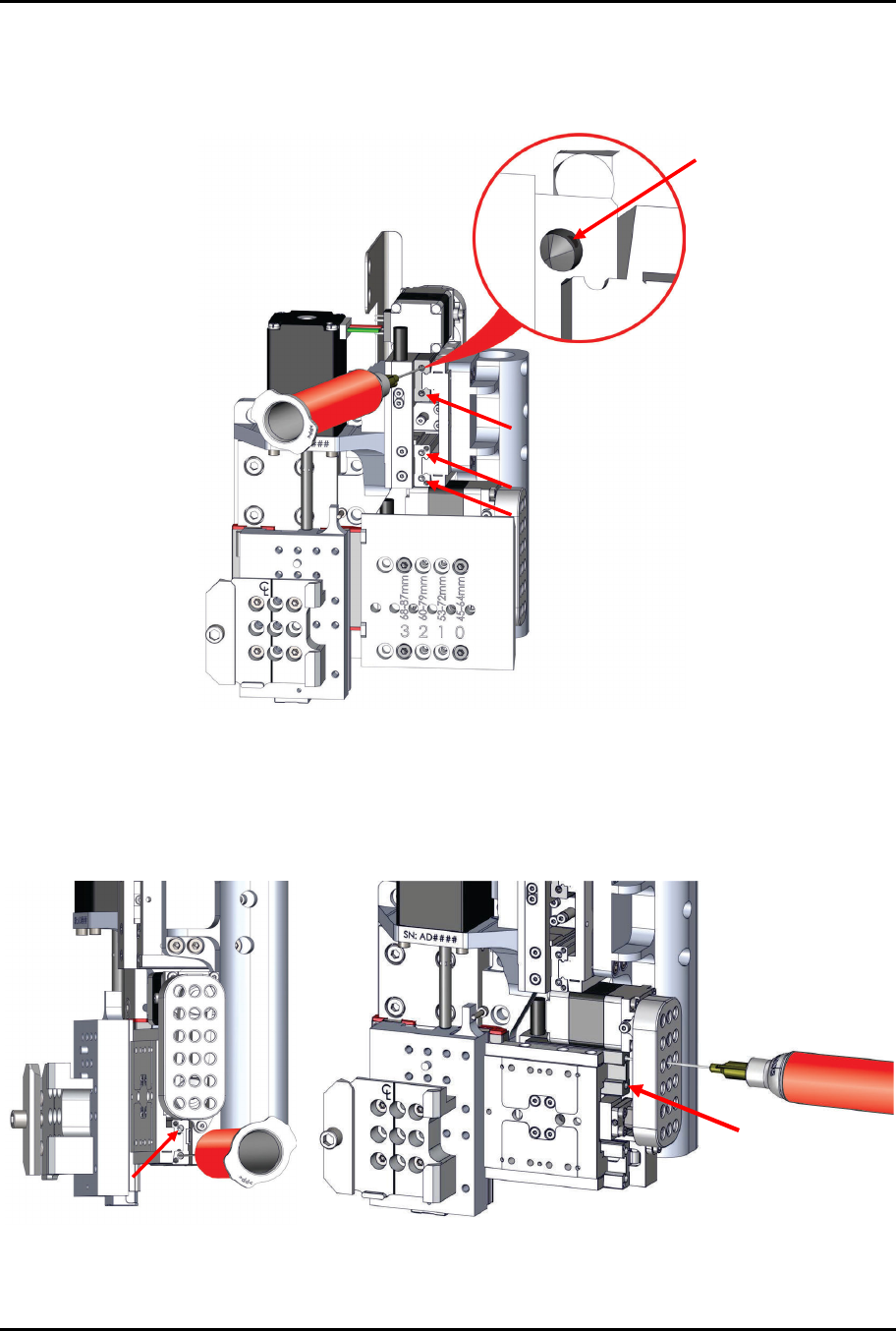
19. Grease the four (4) Y linear bearing by angling the syringe into the bore and injecting
MICROLUBE GL 262 grease into the opening on the side of the bore while moving the axis
full travel (Figure 5-12).
> Clean off excess grease.
Figure 5-12 Y Linear Bearing Grease Locations
20. Grease the four (4) X linear bearings by angling the syringe into the hole and injecting
MICROLUBE GL 262 grease into the opening on the side of the bore while moving the axis
full travel (Figure 5-13).
> The upper locations are accessed through the holes in the cover.
Figure 5-13 X Linear Bearing Grease Locations
ForteMAXDispensingSystemAddendum Maintenance
62 © 2023 Nordson Corporation
21. Loosely install the slide bracket in the position noted during removal.
> The four (4) screws should be loose.
22. While applying a slight downward pressure on the slide bracket so that it is resting, and in
alignment with the alignment length in the back, torque the four (4) screws to
1.3 Nm (12 in-lbs).
23. Power on the dispensing system. Refer to the Forte Dispensing System Installation,
Operations, and Maintenance Manual if necessary.
24. Start the Canvas dispensing software. Refer to the Canvas Dispensing Software User
Guide if necessary.
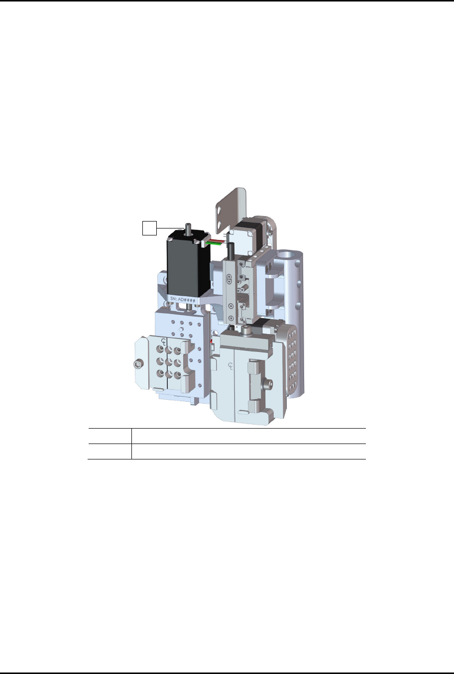
25. After the machine has homed, open the dispensing system hatch and lightly grease the top
half of the Z-axis lead screw with the Super Lube Synthetic Grease (Figure 5-14).
Item Description
1 Z-Axis Lead Screw
Figure 5-14 Lubricating the Z-Axis Lead Screw
26. Reinstall both valves. Refer to the applicable valve manual for installation procedures.
27. Perform a valve offsets procedure. Refer to the Canvas Dispensing Software User Guide if
necessary.
1
© 2023 Nordson Corporation 63
6 Parts Replacement
6.1 Overview
This section includes parts replacement instructions and information for ordering recommended spares
and replacement parts for your dispensing system. This section contains the following procedures:
•
P
art
s Or
deri
ng Infor
m
atio
n
•
Unpackin
g and Insp
ect
in
g Re
placemen
t
P
arts
•
Warran
ty
•
Cleanin
g and Inspe
ction
•
Credi
t and
E
x
chang
e
s
•
S
p
a
r
e
P
a
r
t
s
L
i
s
t
•
Re
cord
Ke
eping
WARNING!
Parts replacement should only be performed by a trained service technician.
Asymtek assumes no liability for personal injury or property damage that may
occur as a result of spare parts being replaced by a non-certified technician.
6.2 Safety First
Operation of the dispensing system involves heat, air pressure, electrical power, mechanical devices, and
the use of hazardous materials. It is essential that every person servicing or operating the dispensing
system fully understands all hazards, risks, and safety precautions. Refer to Section 2 – Safety in this
manual and to the Forte Dispensing System Installation, Operations, and Maintenance Manual for
important safety information.
WARNING!
Perform a service shutdown before replacing parts. Servicing electrical,
pneumatic, or hydraulic components or assemblies that make de-energizing the
whole system impractical, should only be performed by trained personnel. There
should always be a second person present when servicing a system under power.
WARNING!
DO NOT hot swap connections when working with electrical and pneumatic power
supplies. Turn the main circuit break off before disconnecting the external power
plug from the facility.