Forte Max Manual.pdf - 第27页
ForteMAXDispensingSystemAddendum Installation an d Setup © 2023 Nordson Corporation 23 3.7 Dry Valve Offsets Procedur e The following procedure assumes that th e Canvas dispensing software is running. Refer to t he C…
ForteMAXDispensingSystemAddendum Installation and Setup
22 © 2023 Nordson Corporation
b.
Dual Action Dispensing
1) Select the Maintenance button on the Navigation Panel.
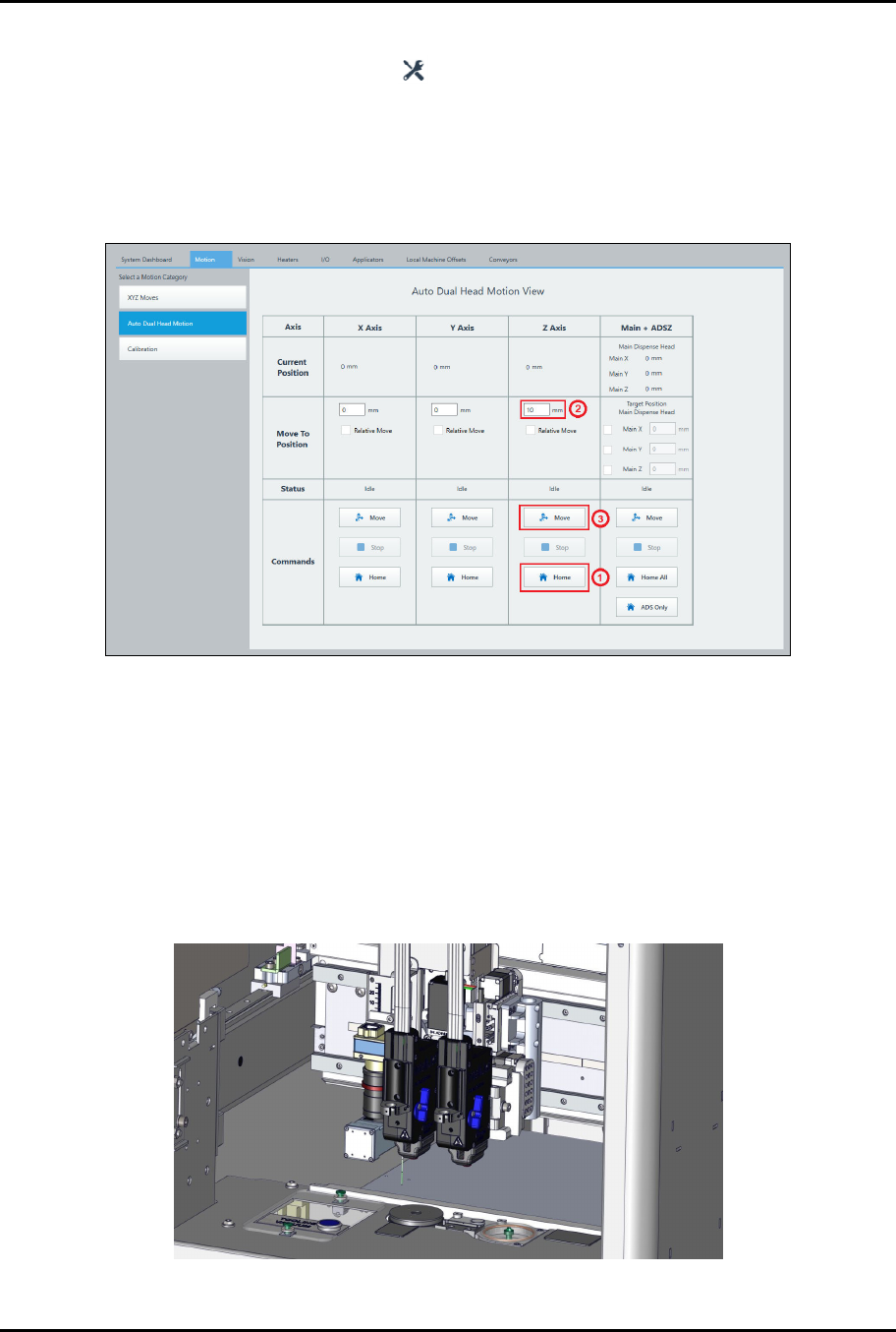
2) Select Motion > Auto Dual Head Motion (Figure 3-19).
3) Click the Home button on the Z-Axis column.
4) Enter 10 mm in the Z-Axis column
5) Click on Move in the Z-Axis column.
Figure 3-19 Valve 1 Adjustment – Dual Toggle
c.
Move both dispense heads down so that the V1 and V2 nozzle tips are close to the
conveyor rail surface.
d.
Visually check the height of the V1 and V2 nozzle tips to see if they are at the same
height (Figure 3-20).
> Acceptable tolerance is ± 8 mm.
e.
If not, remove V1 and adjust the V1 dovetail mount position in the Z-axis until the V1
and V2 nozzle tips are at the same height.
> This step is generally only necessary if the valves are different types.
Figure 3-20 Valves Installed
ForteMAXDispensingSystemAddendum Installation and Setup
© 2023 Nordson Corporation 23
3.7 Dry Valve Offsets Procedure
The following procedure assumes that the Canvas dispensing software is running. Refer to the Canvas
Dispensing Software User Guide for detailed instructions on performing the setup procedures.
To perform a dry valve offsets procedure:
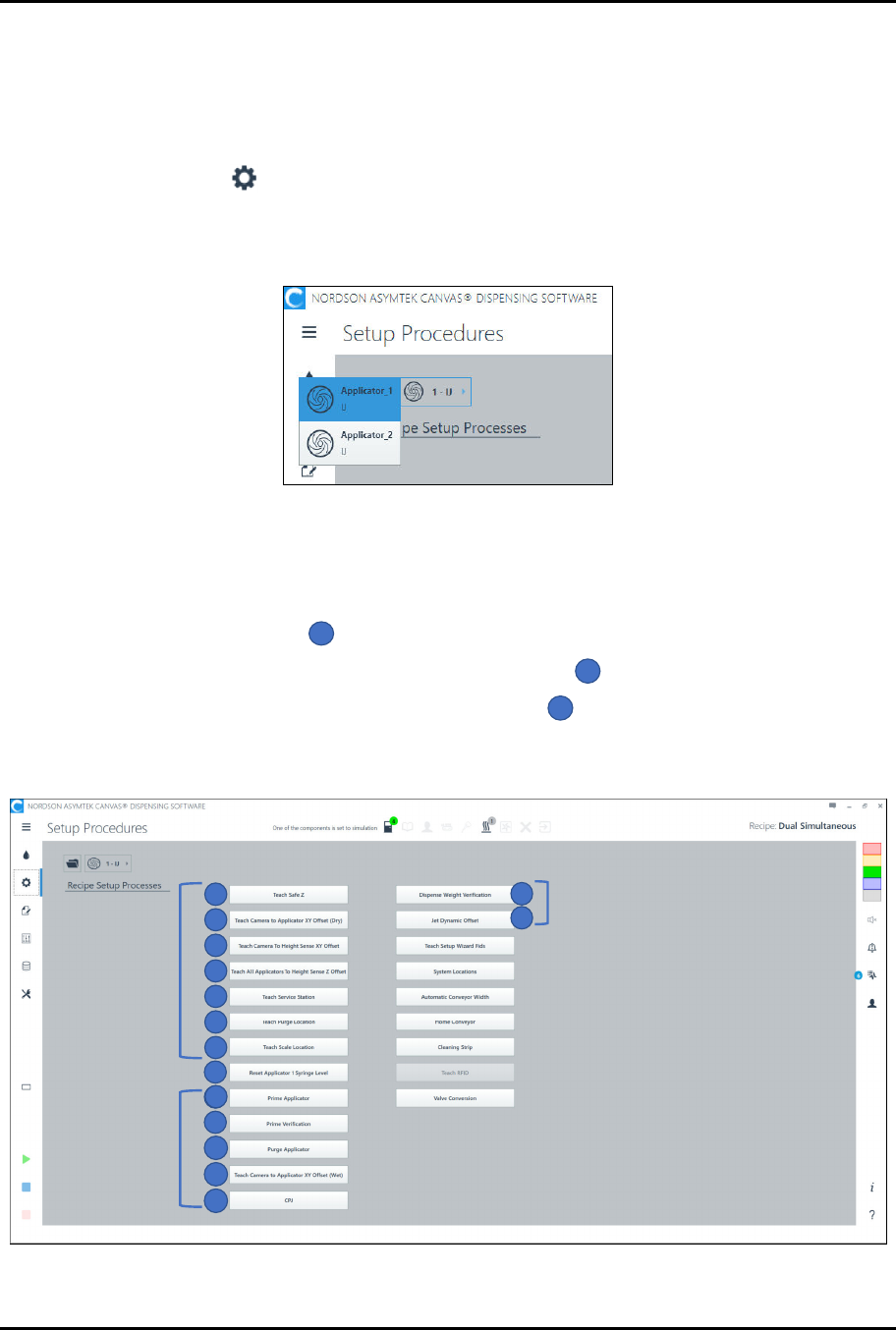
1. Select Setup on the Navigation Panel.
> The Setup Procedures screen opens.
2. Select Applicator 1 (Figure 3-21).
Figure 3-21 Select Valve
3. Perform a dry valve offsets procedure by performing the following steps (numerical
sequence shown in Figure 3-22):
a.
Perform the following steps in sequence for Applicator 1:
1) Teach Safe Z
1
.
2) Teach Camera to Applicator XY Offsets (Dry)
2
.
3) Teach Camera to Height Sense XY Offset
3
.
? The Camera to Height Sense routine may be performed in either V1 or V2
setup. It does not need to be included in both routines.
1
2
3
4
6
7
5
Wet Offsets
9
10
11
12
13
8
9
14
15
Dry Offsets
Wet Offsets
Figure 3-22 Setup Procedures

ForteMAXDispensingSystemAddendum Installation and Setup
24 © 2023 Nordson Corporation
b.
Select Applicator 2 and perform the following step:
1) Teach Camera to Applicator XY Offsets (Dry)
2
.
c.
Select Applicator 1 and perform the following steps in sequence:
1) Teach All Applicators to Height Sense Z Offset
4
.
? When performing "Teach All Applicators to Height Sense Z Offset," the system
will prompt you to teach Applicator 2 first then Applicator 1, since the Delta Z
motor is on Applicator 1. This sequence is specific to the Forte MAX only.
2) Teach Service Station
5
.
? The Teach Service Station routine may be performed in either V1 or V2 setup. It
does not need to be included in both routines.
3) Teach Purge Location
6
.
4) Teach Scale Location
7
.
d.
Select Applicator 2 and perform the following steps in sequence:
1) Teach Purge Location
6
.
2) Teach Scale Location
7
.
4. After the dry offsets are completed, create the recipe, see Section 4 – Recipe Creation.
5. Verify that the "Current Pitch X" value is within 0.250 mm of the "Desired Pitch X" value. If
not, readjust Valve 2 position. Refer to Step 20 and Step 21 under 3.6 Installing the Slide
Bracket and repeat Step 3b and Step 3d under 3.7 Dry Valve Offsets Procedure.
> Wet offset procedures will be performed after the recipe is created. Refer to the Canvas
Dispensing Software User Guide for instructions.