Forte Max Manual.pdf - 第16页
ForteMAXDispensingSystemAddendum Installation an d Setup 12 © 2023 Nordson Corpo ration There are two possible layout options (Figure 3-3 and Figure 3-4). V1 V 1 V2 V2 W orkpiece Origin and W o rkpiece Fid 1 W orkpie…
ForteMAXDispensingSystemAddendum Installation and Setup
© 2023 Nordson Corporation 11
3.4 Designing the Dispense Layout
Prior to setting up the system hardware, you must design the board layout. The slide bracket position
depends on the board layout. Select a board that is as close to perfect as possible when teaching the
board for the first time. This allows the largest room for valve adjustment on a board with a rotated part. If
you start with a board with rotated parts, you may not have the room to adjust.
Select the layout design solution that has the shortest valve pitch within the range of 45 mm to 112 mm.
The longer the distance between Valve 1 (V1) and Valve 2 (V2), the less accurate the dispensing results
and the shorter the X travel (Figure 3-3 and Figure 3-4).
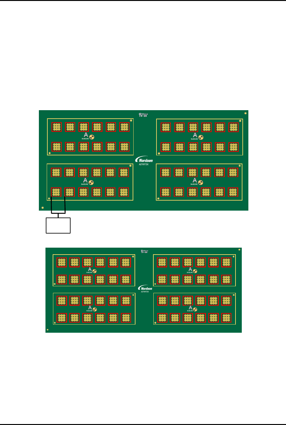
The following multi-up panel board (Figure 3-1) is used as an example for both the dual simultaneous and
dual-action recipes detailed in this manual. The pitch between the parts to be dispensed on (part pitch)
is 16.5 mm.
4,1 4,2 4,3 4,4 4,5 4,6
A2
A1
3,1 3,2 3,3 3,4 3,5 3,6
1 2 3 4 5 6 7 8 9 10 11 12
4
3
2
1
2,1 2,2 2,3 2,4 2,5 2,6
A2
A1
1,1 1,2 1,3 1,4 1,5 1,6
4,1 4,2 4,3 4,4 4,5 4,6
A2
A1
3,1 3,2 3,3 3,4 3,5 3,6
2,1 2,2 2,3 2,4 2,5 2,6
A2
A1
1,1 1,2 1,3 1,4 1,5 1,6
6130139 R EV 1
STRAIGHT
B,1
B,2
Part Pitch
16.5 mm
The application requirement (dispense on all the red squares) is shown in Figure 3-2.
1 2 3 4 5 6 7 8 9 10 11 12
4
3
2
1
6130139 REV 1
STRAIGHT
B,1
B,2
2,1 2,2 2,3 2,4 2 ,5 2,6
1,1 1,2 1,3 1,4 1,5 1,6
4,1 4,2 4,3 4,4 4,5 4,6
A2
A1
3,1 3,2 3,3 3,4 3,5 3,6
A2
A1
4,1 4,2 4,3 4,4 4,5 4,6
A2
A1
3,1 3,2 3,3 3,4 3,5 3,6
A2
A1
2,1 2,2 2,3 2,4 2,5 2,6
1,1 1,2 1,3 1,4 1,5 1,6
Figure 3-2 Application Requirement
F
ig
u
re
3
-
1
M
u
l
t
i
-
U
p
P
a
n
e
l
ForteMAXDispensingSystemAddendum Installation and Setup
12 © 2023 Nordson Corporation
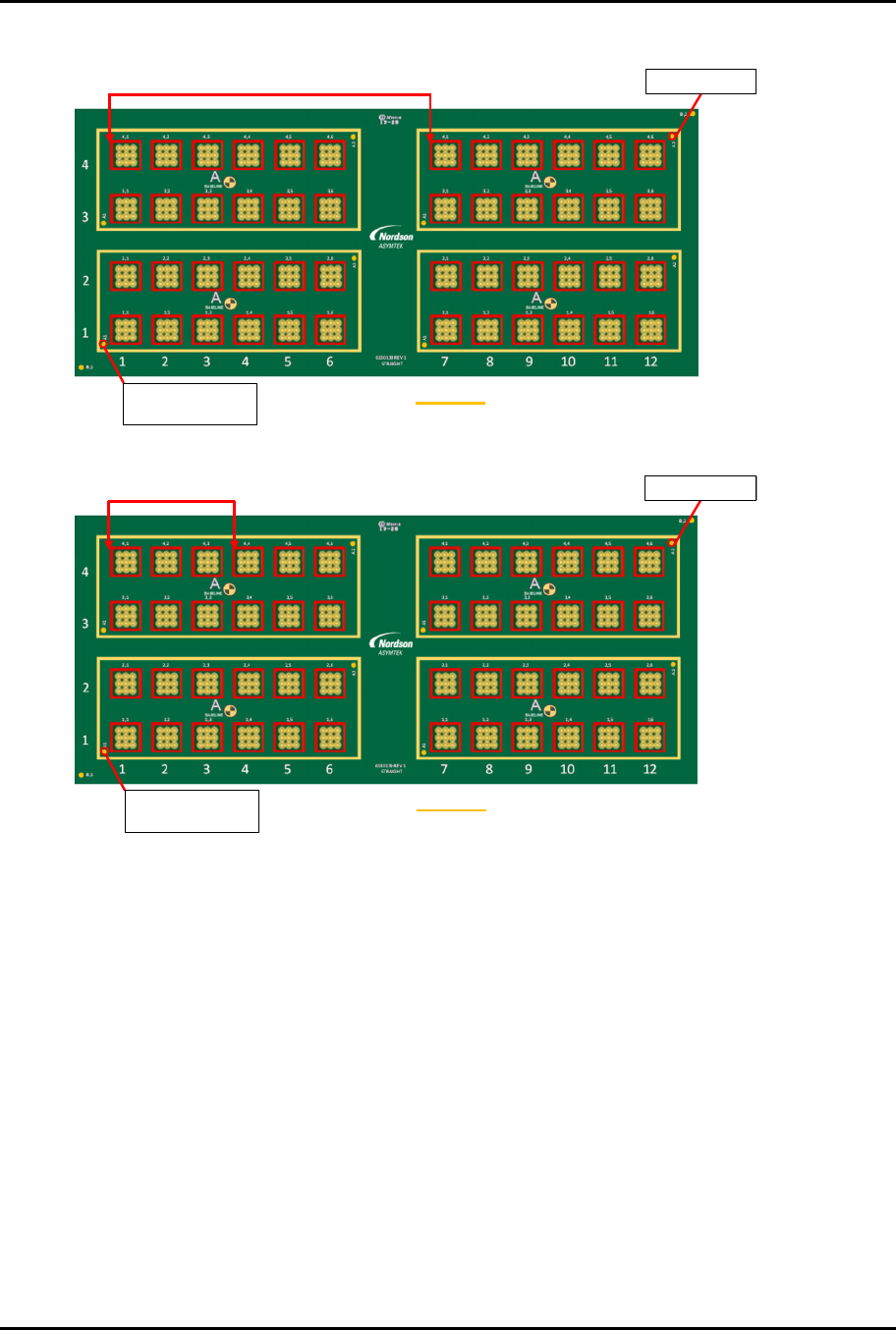
There are two possible layout options (Figure 3-3 and Figure 3-4).
V1
V1 V2
V2
Workpiece Origin
and Workpiece Fid 1
Workpiece Fid 2
Container
Figure 3-3 Layout Option 1
V1
V1 V2
V2
V1
V1 V2
V2
Workpiece Fid 2
Workpiece Origin
and Workpiece Fid 1
Container
Figure 3-4 Layout Option 2
Option 2 is the best option, since the valve pitch for Option 1 is 121.5 mm, which is larger than the
allowable valve pitch range of 45 mm to 112 mm listed in Table 3-1.
ForteMAXDispensingSystemAddendum Installation and Setup
© 2023 Nordson Corporation 13
3.5 Slide Bracket Positions
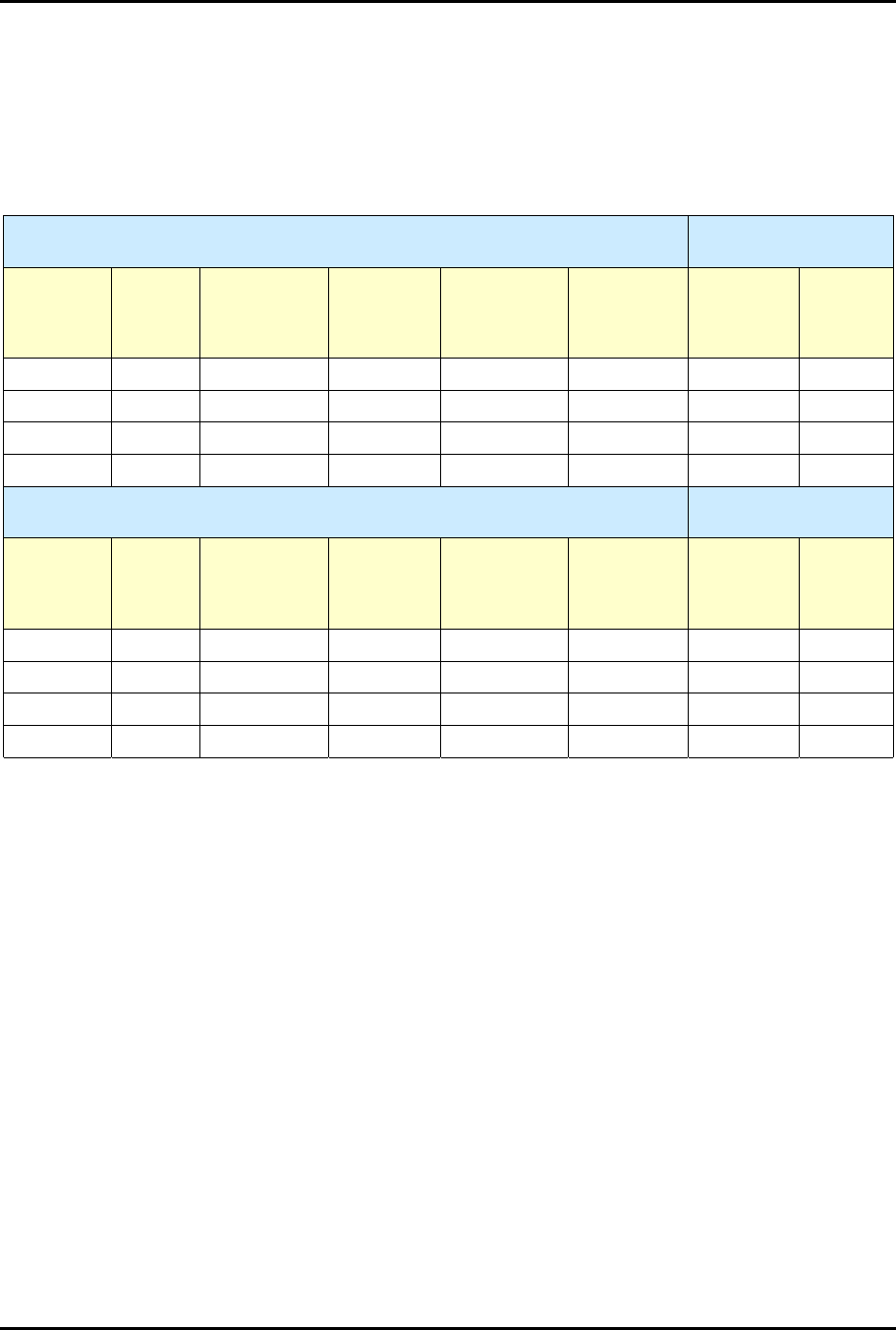
Table 3-1 lists slide bracket positions, corresponding dispense areas, X-Travel Limit settings, and Shock
Stop settings for the various valve pitch ranges.
?
NOTE
The dispense area includes Valve 1, Valve 2, laser height sensor, and camera.
Table 3-1 Slide Bracket Positions
Standard Slide Bracket (Item 221)
Pitch Range 45 mm – 87 mm
Shock Stop 50 mm
(P/N Item 222)
Valve
Pitch
Slide
Bracket
Position
Dispense
Area X
Dispense
Area Y
Two Valves
Only
Dispense
Area X
Two Valves
Only
Dispense
Area Y
X Travel
Limit
Setting
Adjust X
Shock
Stop
45-64 mm 0 223-242 mm 396 mm 266-285 mm 396 mm 330 mm
58 mm
53-72 mm 1 208-227 mm 396 mm 251-270 mm 396 mm 323 mm
66 mm
60-79 mm
2 193-212 mm 396 mm 236-255 mm 396 mm 315 mm
73 mm
68-87 mm
3 178-197 mm 396 mm 221-240 mm 396 mm 308 mm
81 mm
Extended Pitch Slide Bracket (Item 223)
Pitch Range 45 mm – 112 mm
Shock Stop 75 mm
(Item 224)
Valve
Pitch
Slide
Bracket
Position
Dispense
Area X
Dispense
Area Y
Two Valves
Only
Dispense
Area X
Two Valves
Only
Dispense
Area Y
X Travel
Limit
Setting
Adjust X
Shock
Stop
45-89 mm
0
173-217 mm 396 mm 216-260 mm 396 mm 305 mm
83 mm
53-97 mm
1
158-202 mm 396 mm 201-245 mm 396 mm 298 mm
91 mm
60-104 mm
2
143-187 mm 396 mm 186-230 mm 396 mm 290 mm
98 mm
68-112 mm
3
128-172 mm 396 mm 171-215 mm 396 mm 283 mm 106 mm