Forte Max Manual.pdf - 第37页
ForteMAXDispensingSystemAddendum Recipe Creation © 2023 Nordson Corporation 33 4.4.1.5 Placing the Container In this section, we are going to place the c ontain er four (4) times to cover the board. To place the cont…
ForteMAXDispensingSystemAddendum Recipe Creation
32 © 2023 Nordson Corporation
6. Click on Next.
> You will be prompted to teach the column pitch (Figure 4-14).
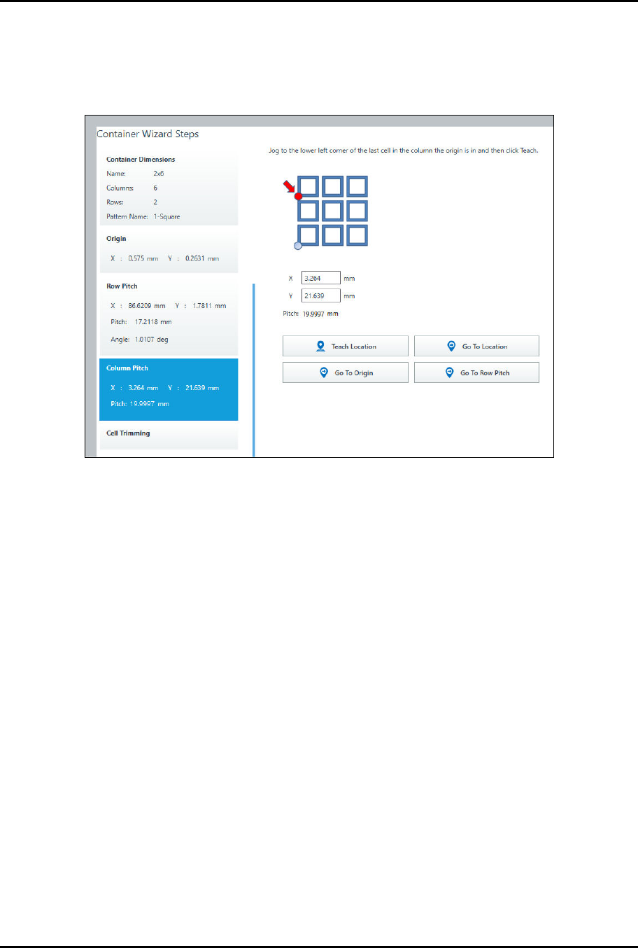
7. To teach the column pitch, jog to the lower left corner of the last cell in the column the
container origin is in and click on Teach Location (Figure 4-12).
Figure 4-14 Teach Column Pitch
8. Click on Next to trim cells, otherwise click on Done.
> Cell trimming allows you to include or exclude specific cells.
> In this example, we will not trim cells.
ForteMAXDispensingSystemAddendum Recipe Creation
© 2023 Nordson Corporation 33
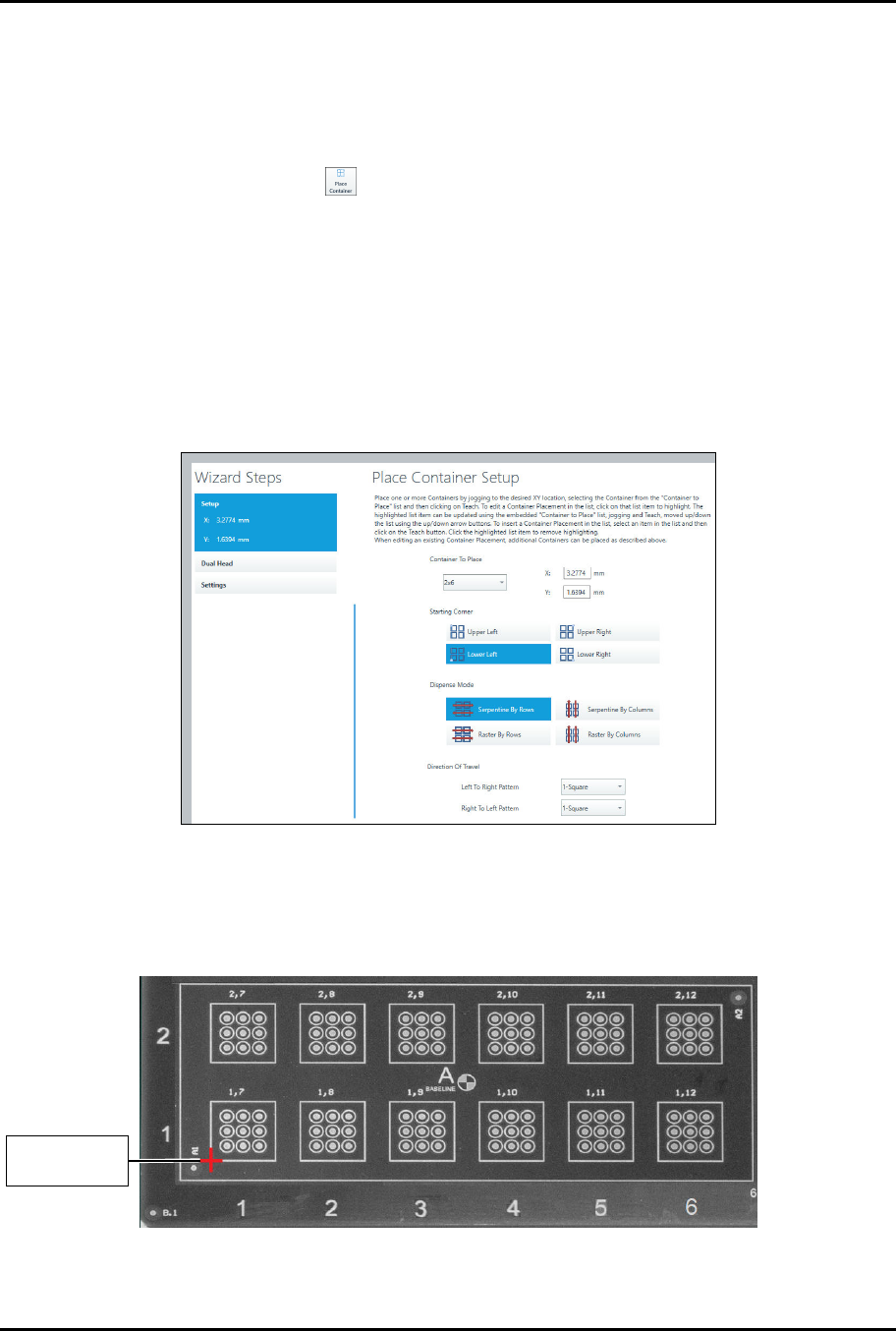
4.4.1.5 Placing the Container
In this section, we are going to place the container four (4) times to cover the board.
To place the container:
1. Select the Workpiece pattern in the Recipe Tree.
2. Select Place Container .
> The Place Container Instruction Wizard opens (Figure 4-15).
3. Select the container to place, starting corner, and dispense mode.
> To reduce total travel distance and cycle time, it is suggested that if the number of
columns is greater than the number of rows, select "Serpentine by Rows." If the number
of rows is greater than the number of columns, select "Serpentine by Columns."
Serpentine modes are typically faster than raster modes.
4. Select Serpentine by Rows and the left-to-right and right-to-left patterns.
> In this example, we have only defined one pattern, so both patterns will be the same.
Figure 4-15 Place Container – Setup
5. Move the camera crosshairs to the container starting corner and click on Teach.
> Since we have selected lower left, the starting corner will be the lower left corner of the
rectangle (Figure 4-16).
Figure 4-16 Container Starting Point
C
o
n
t
a
i
n
e
r
S
t
a
r
t
i
n
g
Corner
ForteMAXDispensingSystemAddendum Recipe Creation
34 © 2023 Nordson Corporation
6. Click on Next.
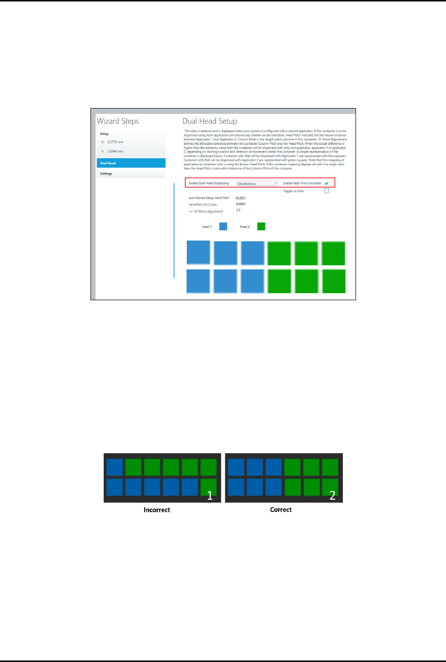
> You will be prompted to enter the dual head settings (Figure 4-17).
7. Select Simultaneous from the drop-down list and Enable Real Time Correction
(Figure 4-17).
> Real-time correction automatically adjusts skewed parts and component height
variation in the x, y, and z-axis.
Figure 4-17 Place Container – Dual Head
8. The Head 1 (blue) and Head 2 (green) boxes indicate Valve 1 and Valve 2 dispensing
locations and should appear as shown in Figure 4-17.
> The blue boxes indicate Valve 1 dispensing locations and the green boxes indicate
Valve 2 dispensing locations.
> If the valve dispensing assignments are different from those shown in Figure 4-17,
verify the pattern again after running a dry valve offsets procedure.
> If the valve dispensing locations are still incorrect, check the container row pitch end to
make sure the pitch end is accurate. Figure 4-18 shows an example of incorrect and
correct valve dispensing locations.
Figure 4-18 Valve Dispensing Locations
9. If desired, select Next to enable multipass, purge, and strip mapping.
10. Click on Done when finished.
> You will return to the Recipe Editor.
> A Do Container instruction appears in the Recipe Tree.
11. Repeat Step 1 through Step 10 for the remaining containers (Figure 4-19).
> To save time, you may also duplicate the container, see Step 12 below.