Forte Max Manual.pdf - 第19页
ForteMAXDispensingSystemAddendum Installation an d Setup © 2023 Nordson Corporation 15 4. Power on the dispensing system. Refer to the Forte Disp ensing System Installation, Operations, and Maintenan c e M anual if n…
ForteMAXDispensingSystemAddendum Installation and Setup
14 © 2023 Nordson Corporation
3.6 Installing the Slide Bracket
?
NOTE
The Forte Max Dispensing System is shipped with the standard slide bracket installed.
This section is included should you need to reinstall or adjust the slide bracket.
To install the slide bracket:
?
NOTE
This procedure assumes that the valve pitch is 50 mm. Since the valve pitch is between
45-64 mm, the standard slide bracket will be installed in Position 0 (Table 3-1). See
Layout Opt
ion 2 (Figure 3-4) under 3.4 Designing the Dispense Layout for layout details.
1. Perform a service shutdown, see 2.11 Service Shutdown.
2. Open the hatch of the Forte Dispensing System.
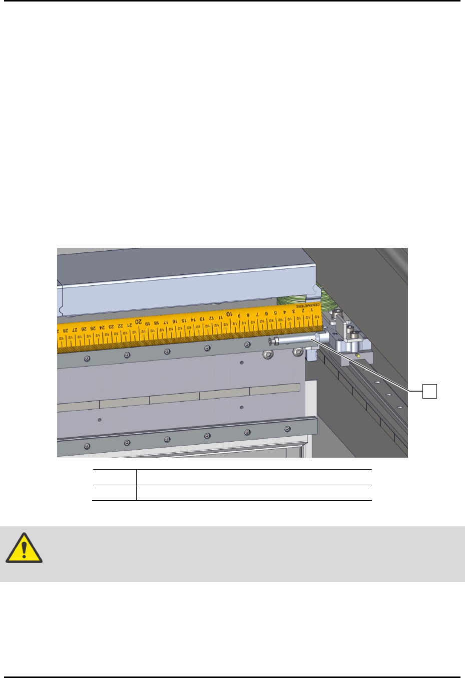
3. Verify that the X Shock Stop screw is installed and set to the proper length depending on
the valve pitch range (Figure 3-5).
> Since the valve pitch is 50 mm, the X Shock Stop screw is set to 58 mm (Table 3-1).
> The shock stop screw is attached to the right Y carriage.
Item Description
1 Shock Stop Screw
Figure 3-5 Shock Stop Screw
CAUTION!
If the shock stop is not set correctly, the dispense head may move too far to the
right and damage the X and Y stages (axes).
1
ForteMAXDispensingSystemAddendum Installation and Setup
© 2023 Nordson Corporation 15
4. Power on the dispensing system. Refer to the Forte Dispensing System Installation,
Operations, and Maintenance Manual if necessary.
5. Start the Canvas dispensing software. Refer to the Canvas Dispensing Software User
Guide if necessary.
6. Verify that the counterbalance pressure is between 483 to 518 kPa (70 to 75 psi).
> The counterbalance regulator and gauge is located in the lower front cabinet.
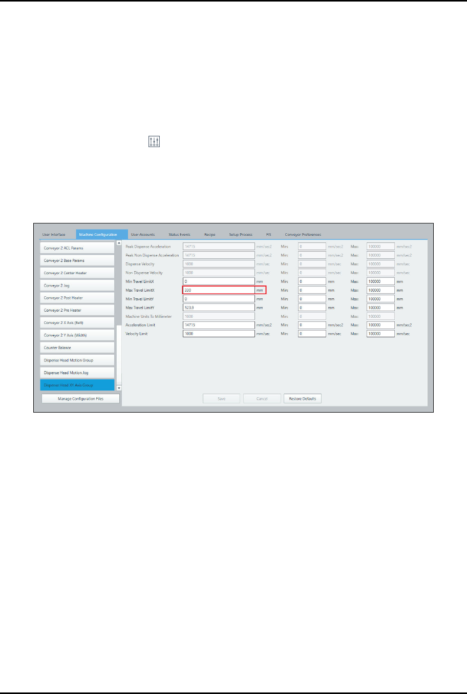
7. Set the X Travel Limit in the Canvas dispensing software.
a.
Select System > Machine Configuration > Dispense Head XY Axis Group.
b.
Set the Max Travel LimitX to 330 mm (Figure 3-6).
> In this example the valve pitch is 50 mm. Since the valve pitch falls within the
45-64 mm pitch range, the X Travel Limit should be set to 330 mm (Table 3-1).
c.
Click on Save.
Figure 3-6 Set Max X Travel Limit
ForteMAXDispensingSystemAddendum Installation and Setup
16 © 2023 Nordson Corporation
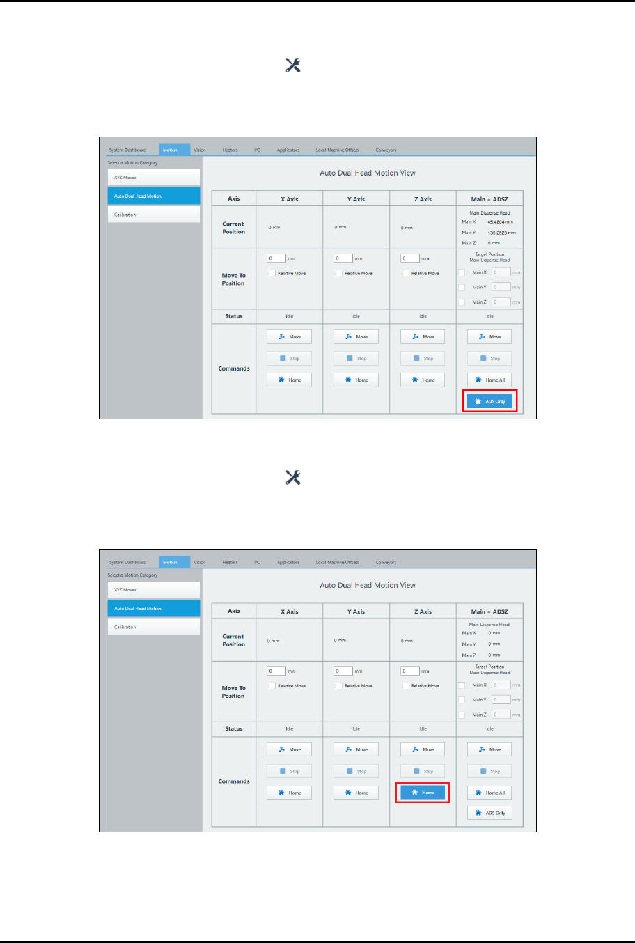
8. Home the Forte MAX bracket.
a.
Auto Dual Simultaneous
1) Select the Maintenance button on the Navigation Panel.
2) Select Motion > Auto Dual Head Motion.
3) Select ADS Only (Figure 3-7).
Figure 3-7 Homing the Bracket – Dual Simultaneous
b.
Dual Action
1) Select the Maintenance button on the Navigation Panel.
2) Select Motion > Auto Dual Head Motion.
3) Click on Home in the Z-axis column (Figure 3-8).
Figure 3-8 Homing the Bracket – Dual Toggle
?
NOTE
Homing the Forte MAX bracket should be the first step performed each time the valve
pitch is changed.