Forte Max Manual.pdf - 第17页
ForteMAXDispensingSystemAddendum Installation an d Setup © 2023 Nordson Corporation 13 3.5 Slide Bracket Posi tions Table 3-1 lists slide bracket positions, corr e sponding dispense areas, X-Travel Limit settings, an…
ForteMAXDispensingSystemAddendum Installation and Setup
12 © 2023 Nordson Corporation
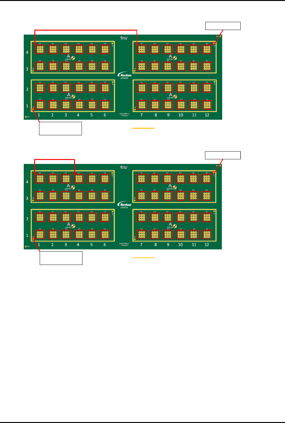
There are two possible layout options (Figure 3-3 and Figure 3-4).
V1
V1 V2
V2
Workpiece Origin
and Workpiece Fid 1
Workpiece Fid 2
Container
Figure 3-3 Layout Option 1
V1
V1 V2
V2
V1
V1 V2
V2
Workpiece Fid 2
Workpiece Origin
and Workpiece Fid 1
Container
Figure 3-4 Layout Option 2
Option 2 is the best option, since the valve pitch for Option 1 is 121.5 mm, which is larger than the
allowable valve pitch range of 45 mm to 112 mm listed in Table 3-1.

ForteMAXDispensingSystemAddendum Installation and Setup
© 2023 Nordson Corporation 13
3.5 Slide Bracket Positions
Table 3-1 lists slide bracket positions, corresponding dispense areas, X-Travel Limit settings, and Shock
Stop settings for the various valve pitch ranges.
?
NOTE
The dispense area includes Valve 1, Valve 2, laser height sensor, and camera.
Table 3-1 Slide Bracket Positions
Standard Slide Bracket (Item 221)
Pitch Range 45 mm – 87 mm
Shock Stop 50 mm
(P/N Item 222)
Valve
Pitch
Slide
Bracket
Position
Dispense
Area X
Dispense
Area Y
Two Valves
Only
Dispense
Area X
Two Valves
Only
Dispense
Area Y
X Travel
Limit
Setting
Adjust X
Shock
Stop
45-64 mm 0 223-242 mm 396 mm 266-285 mm 396 mm 330 mm
58 mm
53-72 mm 1 208-227 mm 396 mm 251-270 mm 396 mm 323 mm
66 mm
60-79 mm
2 193-212 mm 396 mm 236-255 mm 396 mm 315 mm
73 mm
68-87 mm
3 178-197 mm 396 mm 221-240 mm 396 mm 308 mm
81 mm
Extended Pitch Slide Bracket (Item 223)
Pitch Range 45 mm – 112 mm
Shock Stop 75 mm
(Item 224)
Valve
Pitch
Slide
Bracket
Position
Dispense
Area X
Dispense
Area Y
Two Valves
Only
Dispense
Area X
Two Valves
Only
Dispense
Area Y
X Travel
Limit
Setting
Adjust X
Shock
Stop
45-89 mm
0
173-217 mm 396 mm 216-260 mm 396 mm 305 mm
83 mm
53-97 mm
1
158-202 mm 396 mm 201-245 mm 396 mm 298 mm
91 mm
60-104 mm
2
143-187 mm 396 mm 186-230 mm 396 mm 290 mm
98 mm
68-112 mm
3
128-172 mm 396 mm 171-215 mm 396 mm 283 mm 106 mm
ForteMAXDispensingSystemAddendum Installation and Setup
14 © 2023 Nordson Corporation
3.6 Installing the Slide Bracket
?
NOTE
The Forte Max Dispensing System is shipped with the standard slide bracket installed.
This section is included should you need to reinstall or adjust the slide bracket.
To install the slide bracket:
?
NOTE
This procedure assumes that the valve pitch is 50 mm. Since the valve pitch is between
45-64 mm, the standard slide bracket will be installed in Position 0 (Table 3-1). See
Layout Opt
ion 2 (Figure 3-4) under 3.4 Designing the Dispense Layout for layout details.
1. Perform a service shutdown, see 2.11 Service Shutdown.
2. Open the hatch of the Forte Dispensing System.
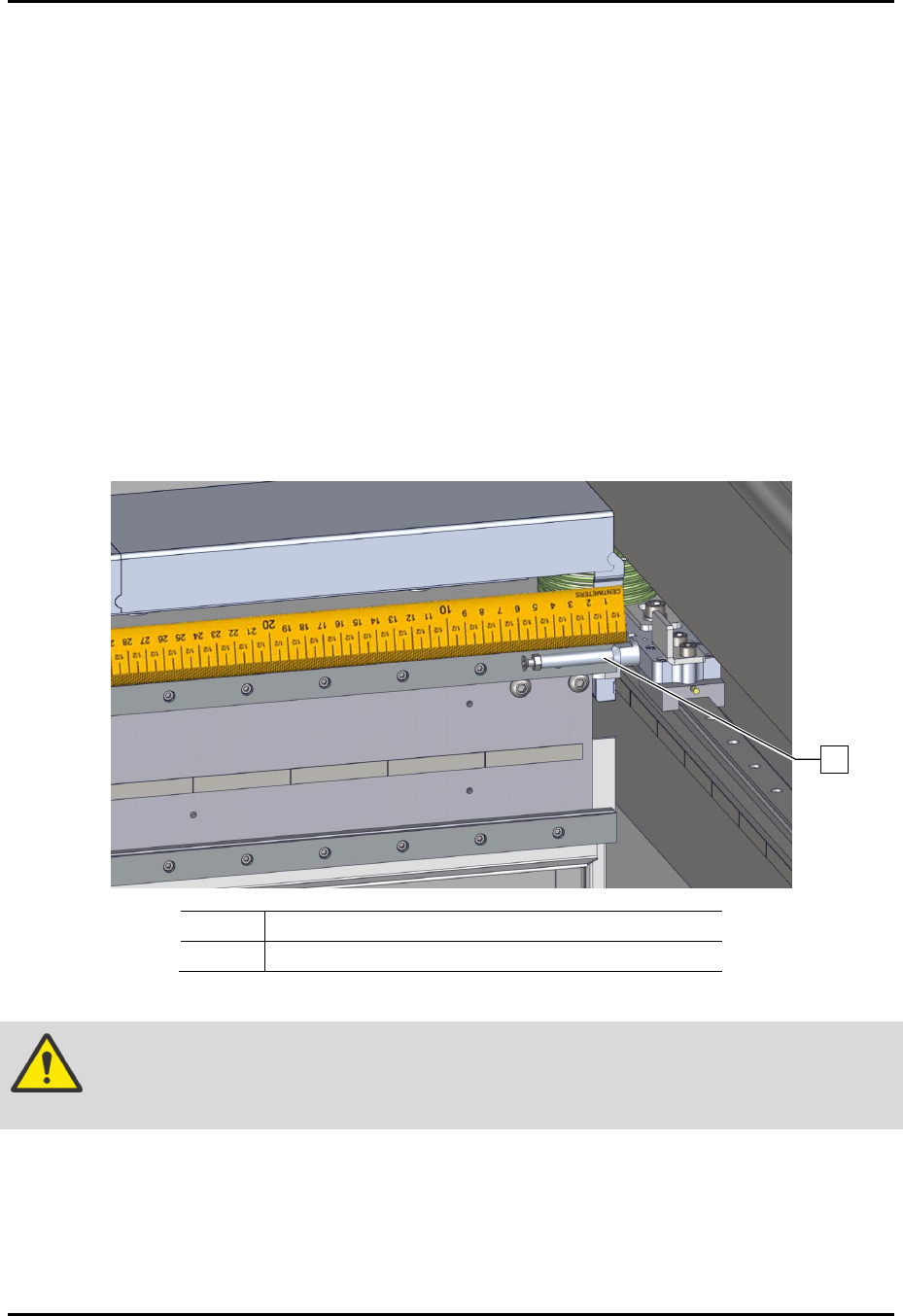
3. Verify that the X Shock Stop screw is installed and set to the proper length depending on
the valve pitch range (Figure 3-5).
> Since the valve pitch is 50 mm, the X Shock Stop screw is set to 58 mm (Table 3-1).
> The shock stop screw is attached to the right Y carriage.
Item Description
1 Shock Stop Screw
Figure 3-5 Shock Stop Screw
CAUTION!
If the shock stop is not set correctly, the dispense head may move too far to the
right and damage the X and Y stages (axes).
1