Tracker-2800-2800S.pdf - 第13页
13 2-3. Channel Selection There are two channels on th e Tracker 2800 (channel A and channel B ) which are selected b y pressing the appropriate front panel button. W hen using a single channel, the red probe should be p…
12
2-2 Getting started with the Tracker 2800/2800S
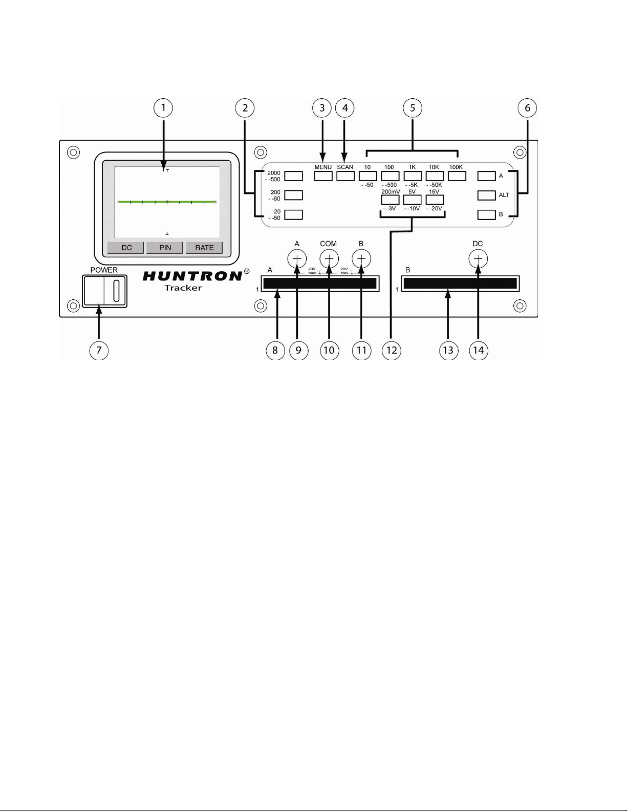
Figure 2-2 Tracker 2800/2800S Overview (Shown with “Power-up” menu on LCD)
1. LCD Display 2. Frequency buttons 3. Menu button
4. Scan button 5. Resistance buttons 6. Channel Select buttons
7. Power switch 8. Ch. A 2800S connector 9. Ch. A banana jack
10. Common banana jack 11. Ch. B banana jack 12. Voltage buttons
13. Ch. B 2800S connector 14. DC Voltage Source banana jack
Connect the Tracker 2800 or 2800S to power.
Turn the Tracker 2800 ON using the front panel power switch. The “Power-up” menu will be
displayed on the LCD touch screen.
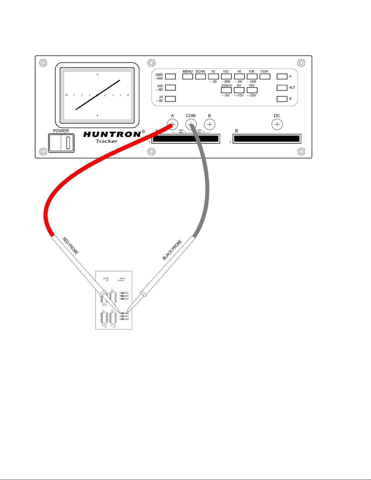
Insert your Huntron Microprobes into the shrouded banana jacks marked Channel A (or
Channel B) and Common as shown in Figure 2-3. Typically, the red Microprobe lead will be
used in the Channel A (or B) connection and the black Microprobe used in the Common
connection.
Proceed to test components on a powered off circuit board by holding the tips of the test probes
to the component pins.
Touching the signature area on the LCD touch screen will toggle from full screen signature
display to signature display with text information. NOTE: Use only your fingers to activate
the Tracker touch screen. Using pens, probes or any sharp device can result in damage to
the screen.
13
2-3. Channel Selection
There are two channels on the Tracker 2800 (channel A and channel B) which are selected by pressing
the appropriate front panel button. When using a single channel, the red probe should be plugged into
the corresponding channel test terminal and the black probe or common test lead should be plugged
into the common test terminal. When testing, the red probe should be connected to the positive
terminal of a device (i.e. anode, +V, etc.) and the black probe should be connected to the negative
terminal of a device or a common reference (i.e. cathode, ground). Following this procedure should
assure that the signature appears in the correct quadrants of the LCD display.
Figure 2-3
Manual probing of
components on a printed
circuit board is accomplished
using hand held probes
connected to the Tracker 2800
front panel.
14
2-4 Alternate Mode
The Alternate (ALT) mode of the Tracker 2800 is provided to automatically switch back and forth
between Channel A and Channel B. This allows easy comparison between two devices or the same
points on two circuit boards. The Alternate mode is selected by pressing the ALT button on the front
panel. The alternation frequency is varied by pressing the RATE control button on the Tracker LCD
then pressing the and buttons until the desired alternation frequency is reached. The RATE is
numbered from 1 (fastest) to 10 (slowest). Press the RATE button to return to the power-up menu.
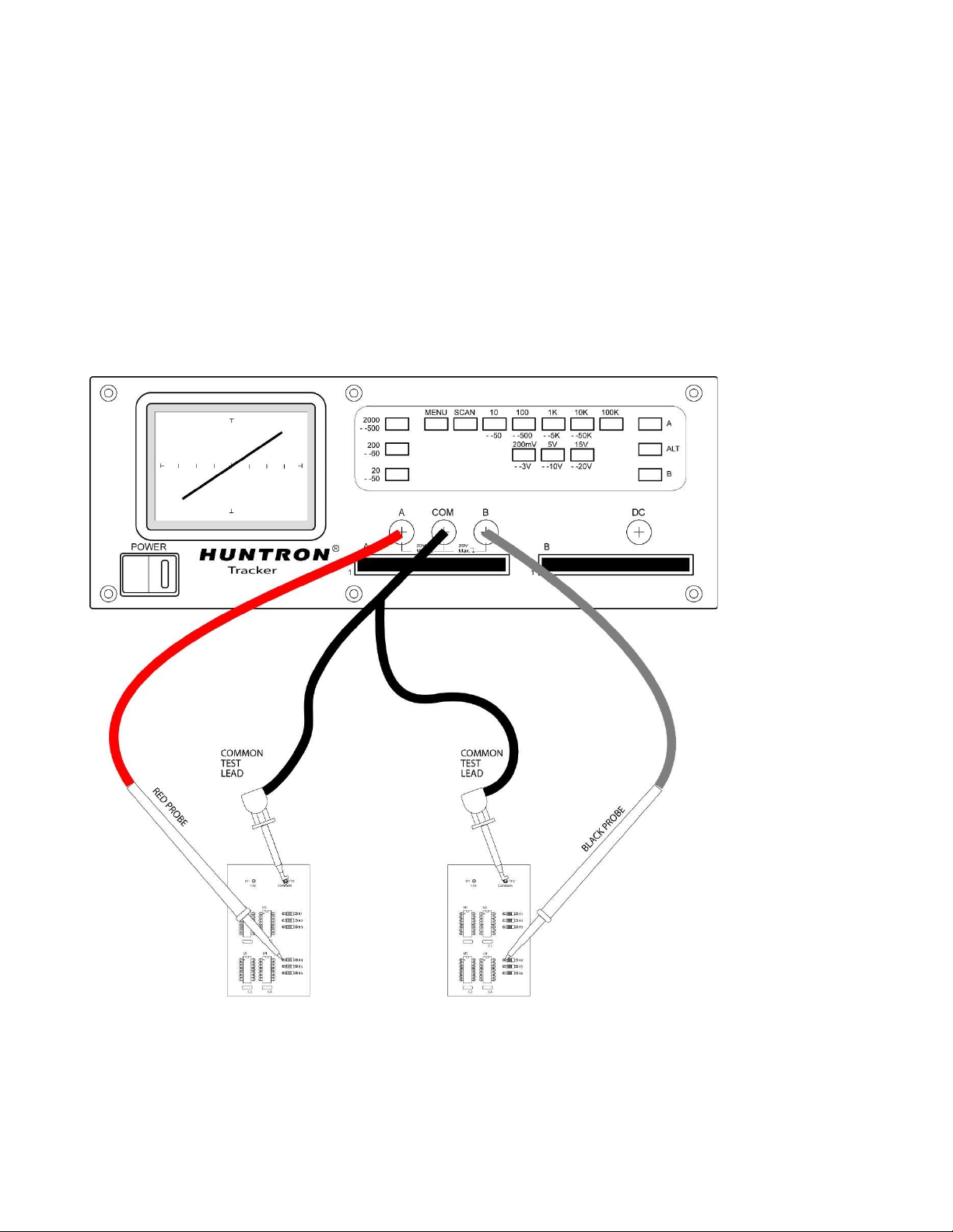
Figure 2-4 shows how the instrument is connected to a known good board and a board under test. This
test mode uses the supplied common test leads to connect two equivalent points on the boards to the
common test terminal. Note that the black probe is plugged into the channel B test terminal.
When using ALT mode, a green check mark or red “X” on the bottom right portion of the LCD will
indicate a pass or fail comparison.
Figure 2-4
Channel A and B
with the ALT mode
can be used to make
direct comparisons
of two PCBs.