Tracker-2800-2800S.pdf - 第73页
73 6. Place the red test probe to th e SCR's anode lead and th e black test probe to the SCR's cathode le ad. 7. Observe the SCR's anode-gate si gnature. Gate-Anode Gate-Cathode Anode-Cathode Figure 4-31 .…
72
MRD3056 With No Light MRD3056 With Light
Figure 4-29. Signatures of a NPN C-E Junction Phototransistor at 15V and 1K.
The phototransistor's signature is similar to a diode's signature in reverse breakdown mode when not
activated by light and as a short signature when activated by a bright external light.
SCRs and TRIACs
A SCR and TRIAC are semiconductor components that are used in switching applications. A SCR
(silicon controlled rectifier) is used for DC switching circuits. A TRIAC is used for AC switching
circuits. This section will demonstrate how to dynamically test these components.
Silicon Controlled Rectifiers (SCR’s)
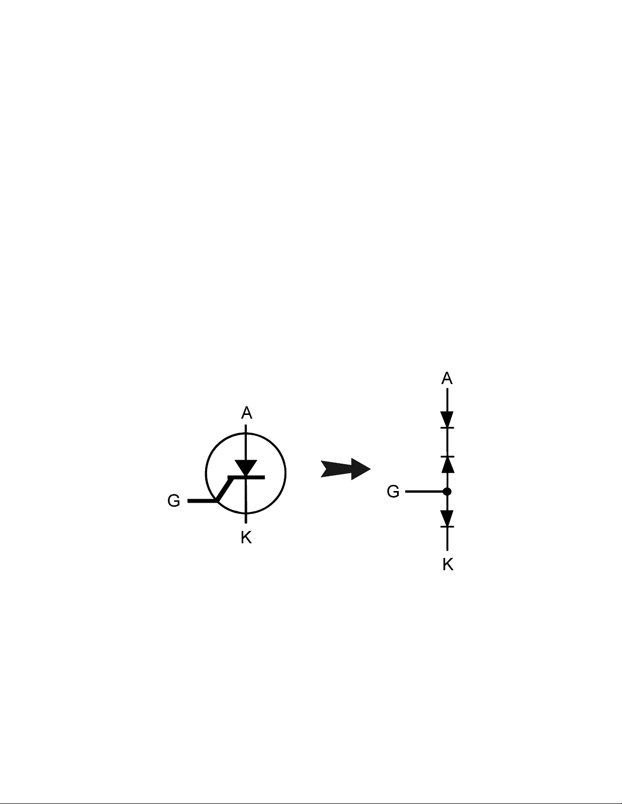
The SCR is a switching semiconductor device that conducts positive current only. Its symbol and
equivalent circuit can be seen below. When the gate (G), is at the same voltage level as the cathode
(K), the SCR acts like an open. When the gate (G) is forced more positive than the cathode (K),
positive current flows between the anode (A) and the cathode (K).
Figure 4-30. Diagram of a Silicon Controlled Rectifier.
Do the following to display the analog signature of a SCR:
1. Select the 20V, 10K and 60Hz.
2. Place or clip the red test probe from the Tracker 2800's Channel A jack to gate lead (G) of the
component.
3. Observe the gate-anode signature of the SCR.
4. Move the black test probe from the SCR's anode lead to cathode lead (K) of the component.
5. Observe the gate-cathode signature of the SCR.
73
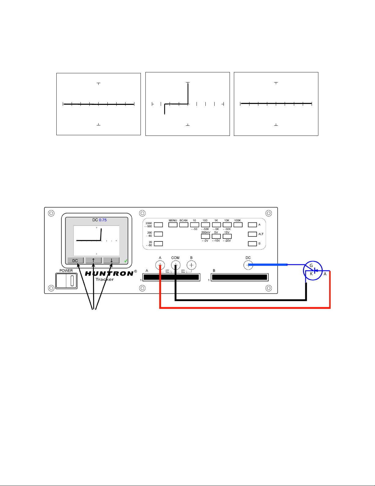
6. Place the red test probe to the SCR's anode lead and the black test probe to the SCR's cathode lead.
7. Observe the SCR's anode-gate signature.
Gate-Anode Gate-Cathode Anode-Cathode
Figure 4-31. Signatures of a SCR - C106B Type at 20V and 10K.
8. Connect the Tracker 2800 DC Voltage Source to the Gate. Increase the DC Voltage Source level
while observing the anode-cathode signature.
Figure 4-32. Testing a SCR using the DC Voltage Source
Review
Solid state photosensitive switch components are turned on by light.
SCRs and TRIACs are solid state switches that are turned on by a control input pin called a gate. SCRs
conduct current in one direction while TRIACs conduct current in both directions.
Applications
The SCR and TRIAC can also be a problem to troubleshoot. They may be used to switch large
currents. Quite often these components are susceptible to degradation and eventual failure. The Tracker
can easily show these failure.
Using the arrows buttons to
increase/decrease the DC voltage level

74
SECTION 5 TESTING INTEGRATED CIRCUITS
5-1. DIGITAL INTEGRATED CIRCUITS
Digital integrated circuit (IC) chips are made from transistors on a common substrate. Their analog
signatures are typically variations of the discrete diode and transistor signatures. Most logic ICs,
contain multiple circuits in one chip. These chips can have pins from 14 to over 200, although quite
often many pins share quite similar signatures. This can make troubleshooting easier by giving us an
easy-to-find signature to use as a comparison. In this section, it is important to understand how the
Tracker 2800 and ASA respond to these circuits.
Integrated Circuit Failures
A functioning IC may stop working for a number of reasons. Some of the most common causes of IC
failures are:
EOS - Electrical Over Stress. The IC’s maximum electrical specifications have been exceeded. This
condition may result in the IC developing internal shorts and opens.
ESD - Electrostatic Discharge. Repeated exposure may cause internal resistance to develop in the
IC junctions. This internal resistance may vary from 5 k to 25 k with a typical value of 20 k. ESD
exposure can cause internal flaws such as resistance, opens and shorts.
Dendrites - A process flaw, that results in particles growing between conductors on a substrate
causing shorts.
Ionic - Contamination introduced at the time of manufacturing that contamination develops into
leakage between substrate channels. This causes 5 k to 25 k of resistance.
Purple Plague - Destructive interaction between gold and aluminum metal layers. Junction
connections become very brittle and may cause internal opens.
Corrosion or Electromigration - Another process flaw in which aluminum metallization causes
pinholes, corrosion and resistance. This will create opens and resistance.