Tracker-2800-2800S.pdf - 第70页
70 B-E Junction C-E Junction C-B Junction Figure 4-27 . Signature of a Da rlington Transistor, TIP112 NPN T ype at 20V and 20K . Note that the B-E junction has a sloped leg bend i n its signature caused b y internal re…
69
8. Now that you know that pin 2 of the unknown transistor is the collector. Place the black probe to the
base on pin 1 and move the red probe to the emitter on pin 3. A base to emitter signature will be
displayed. This transistor is a NPN type since the base-emitter signature matches a NPN transistor.
Figure 4-25. Signature of Pins 1 and 3 of an Unknown Transistor.
Darlington Bipolar Transistor Signatures
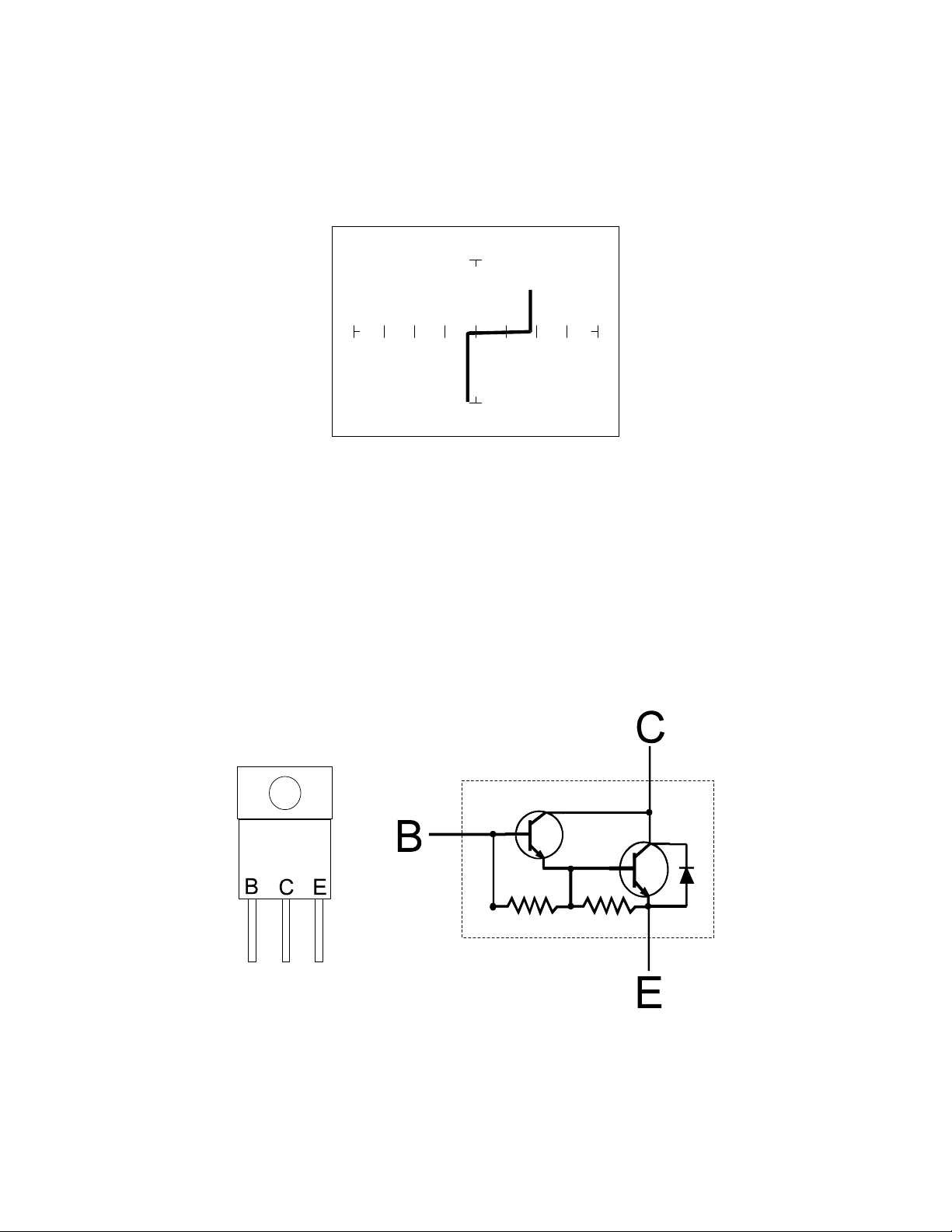
The Darlington transistor is basically two transistors paired together in a special configuration. The
emitter of the first transistor is connected to the base of the second transistor. The collectors of both
transistors are connected together. The base of the first transistor serves as the external base lead and
the emitter of the second transistor serves as the external emitter lead. A block diagram of a Darlington
transistor and its analog signature are shown in the following figures.
Figure 4-26. Diagram of a Darlington Transistor.

70
B-E Junction C-E Junction C-B Junction
Figure 4-27. Signature of a Darlington Transistor, TIP112 NPN Type at 20V and 20K.
Note that the B-E junction has a sloped leg bend in its signature caused by internal resistors R1 and R2.
Review
A PNP bipolar transistor consists of a layer of N-type silicon sandwiched between two layers of P-
type silicon.
A NPN bipolar transistor consists of a layer of P-type silicon sandwiched between two layers of N-
type silicon.
To test a transistor, the base-emitter (B-E), collector-base (C-B) and collector-emitter (C-E)
junctions all need to be examined.
The transistor signature resembles the diode signatures previously examined. They have polarity
and may exhibit the Zener effect.
Applying What We Have Learned
Transistors will display the same type of faulty signature as diodes, with a rounded “knee” and
non-linear or resistive current and voltage legs.
The Tracker 2800 can be used to determine the type of transistor; bipolar, Darlington, FET, etc.
The Tracker 2800 can be used to identify the polarity of a transistor (PNP or NPN).
The Tracker 2800 can be used to determine the base, collector and emitter on an unknown
transistor.
The Tracker 2800 can be used to match the gain (beta) of two transistors.
The above techniques of identification are invaluable when repairing foreign electronics and
systems without schematics.
71
4-3. SOLID STATE SWITCHING COMPONENTS
Optical Switches
There are two types of optical switches: phototransistors and optocouplers. Phototransistors can be
used in two modes depending on the application. It can be used as either a light activated transistor or
as a light activated diode. In either mode, light is used to turn it on and allow current to flow.
The optocoupler consists of a light emitting diode and a phototransistor in the same package. They are
electrically isolated. When the diode is turned on by an external signal, it radiates light. This light falls
on the phototransistor base junction that results in the device turning on.
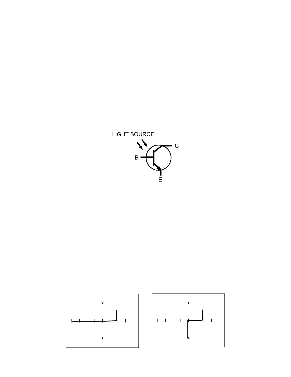
Phototransistor
Figure 4-28. Phototransistor Schematic Diagram.
Do the following to display the analog signature of a phototransistor:
1. Select the 1K and 15V.
2. Place or clip the red test lead from the Tracker 2800's Channel A jack to collector lead of the
component.
3. Place or clip the black test lead from the Tracker 2800's Common jack to emitter lead of the
component.
4. Observe the signature of the phototransistor
5. Direct a light source at the phototransistor and observe the signature change.