Tracker-2800-2800S.pdf - 第31页
31 SCAN – P A CK AGE Controls (Tracker 2800S ) When scanning with a Tr acker 2800S, it is possible to configure the pin counti ng order used on the front panel cable connectio ns. Depending on the type of component that …
30
SCAN – MODE Controls
The SCAN – MODE controls how the Tracker will step through a selected range parameter when the
Scan mode is started by pressing the SCAN front panel button. The SCAN mode can step through
voltage (VOL), resistance (RES), frequency (FREQ) or NONE. To set the SCAN mode, press the
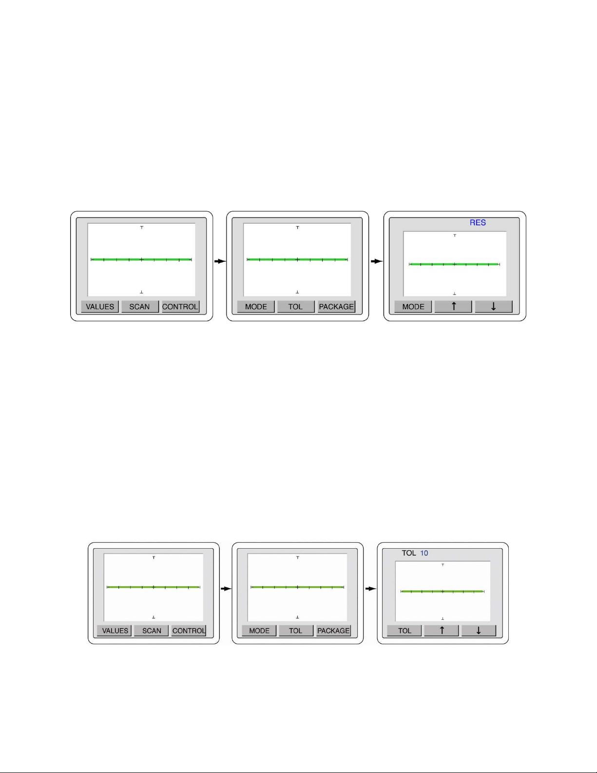
MENU front panel button to display the Main menu (left image in figure 2-24). Press the SCAN
button to display the SCAN menu (middle image in figure 2-24). Press the MODE button to display
the MODE menu (right image in figure 2-24). Use the and arrow buttons to step the selections of
voltage (VOLT), resistance (RES), frequency (FREQ) or NONE.
Figure 2-24 SCAN - MODE menus
Press the MENU front panel button three times to return to the power-up menu or press the MODE
button to go back to the SCAN menu. The range combinations used when scanning are controlled
within the Smart Tracker Active Range limits (see section 2-10).
SCAN – TOL (Tolerance) Controls
The SCAN – TOL controls the tolerance allows when the signature on channel A is compared against
the signature on channel B. The tolerance is adjustable from 0 to 90. The larger the tolerance, the
greater the two signatures can differ and still be considered a “pass” when compared against each
other. To access the SCAN – TOL control menus, press the MENU front panel button to display the
Main menu (left image in figure 2-25). Press the SCAN button to display the SCAN menu (middle
image in figure 2-25). Press the TOL button to display the MODE menu (right image in figure 2-25).
Use the and arrow buttons to adjust the tolerance value to the desired setting.
Figure 2-25 SCAN – TOL menus
It is recommended that a low setting such as 5 or 10 be used for general purpose comparison
troubleshooting.
31
SCAN – PACKAGE Controls (Tracker 2800S)
When scanning with a Tracker 2800S, it is possible to configure the pin counting order used on the
front panel cable connections. Depending on the type of component that is connected to during
scanning, the package type and number of pins will need to be configured.
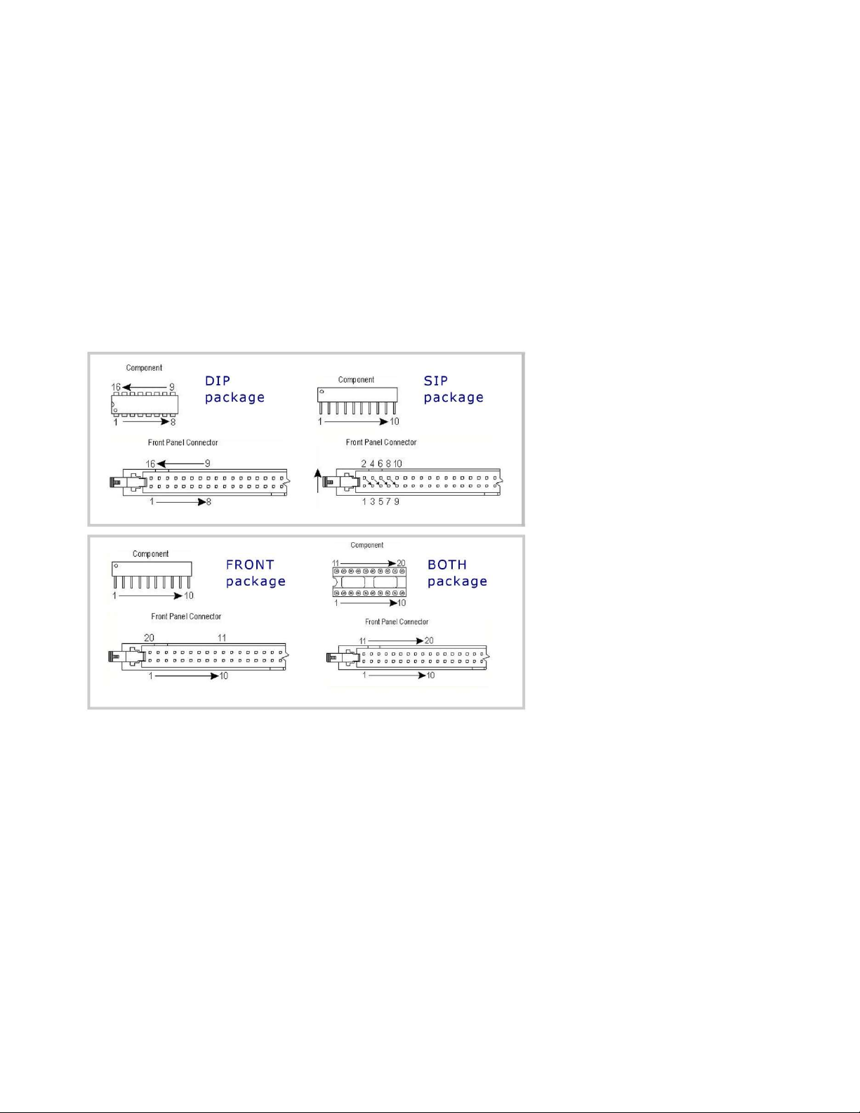
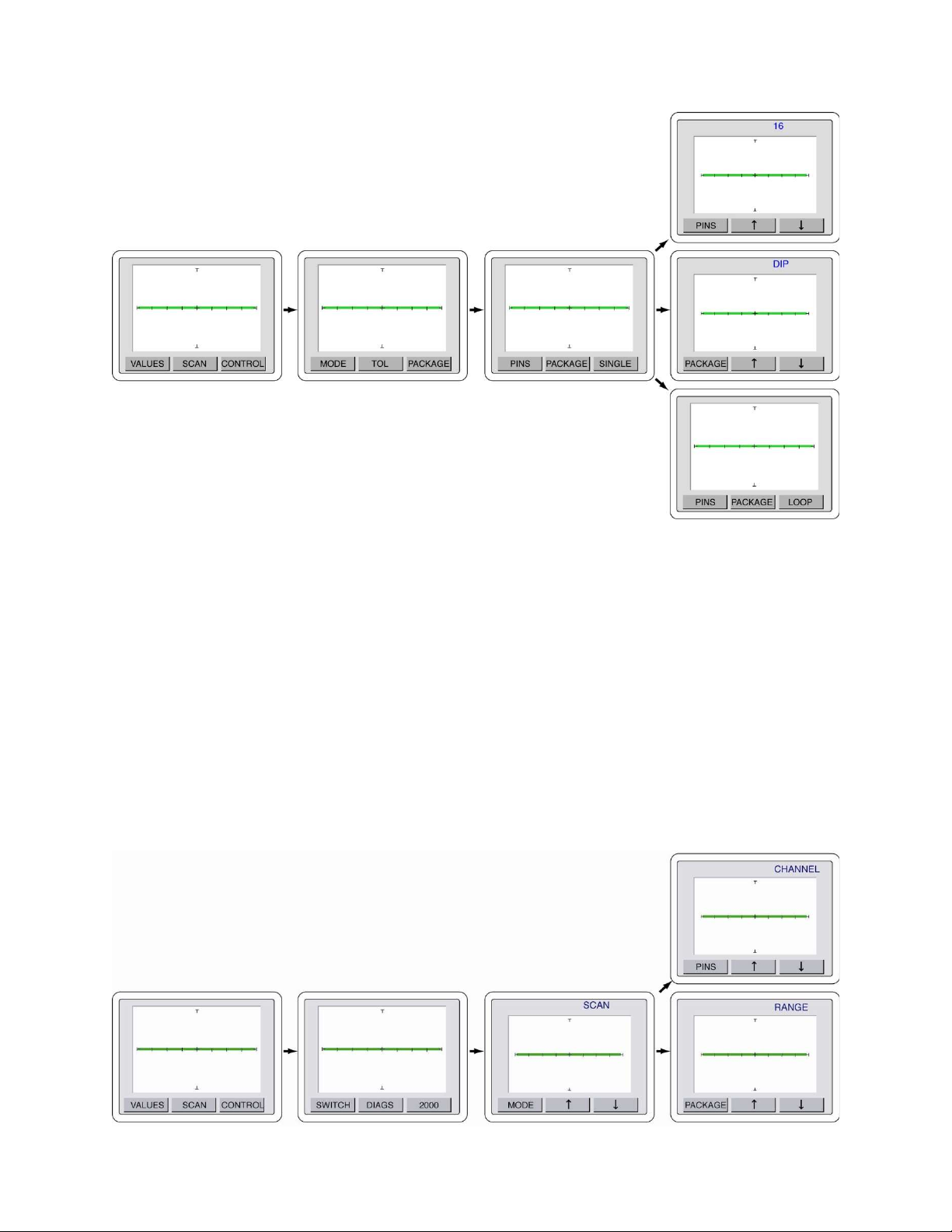
To configure the scan package type press the Menu front panel button to display the Main menu (first
image in figure 2-27). Select SCAN from the touch screen Main menu to display the SCAN menu
(second image in figure 2-27). Select PACKAGE from the SCAN menu to display the PACKAGE
menu (third image in figure 2-27). Select PACKAGE to display the PACKAGE select menu (middle
right image in figure 2-26). Use the and buttons to step up or down through the package choices of
DIP, SIP, BOTH or FRONT (see figure 2-26).
Press the PACKAGE button to return to the Package menu. Press the PINS button to display the PIN
select menu (top right image in figure 2-27). Use the and buttons to increase or decrease the
numbers of pins to be scanned. Press the PINS button to return to the PACKAGE menu.
You can also configure how the scan is executed when the SCAN button is pressed. Press the SINGLE
button to toggle (bottom right image in figure 2-27) between SINGLE (single pass then stop), LOOP
(continuous scan) or STOP (stop on failure).
Figure 2-26 Scan package types
32
Figure 2-27. Scan/Package menus
Press the MENU front panel button three times to return to the power-up menu.
CONTROL – SWITCH Controls
The CONTROL – SWITCH menu controls the function of the optional footswitch when used with the
Tracker 2800.
To configure the footswitch control press the front panel MENU button to display the Main menu on
the LCD (left image in figure 2-28). Press the CONTROL button on the LCD to display the Control
menu (image second from left in figure 2-28). Press the SWITCH button on the LCD to display the
Switch menu (image third from left in figure 2-28). Use the and arrow buttons to select the
footswitch control between SCAN (image third from left in figure 2-28), CHANNEL (middle image
on right in figure 2-28) and RANGE (bottom image on right in figure 2-28).