Tracker-2800-2800S.pdf - 第28页
28 Figure 2-20 DC Voltage Source menu controls Press the DC button to re turn to the power-up screen. PIN Contro ls (Track er 2800S) Stepping through individual pins with th e Tracker 2800S is accomplished using the touc…
27
The footswitch controls work as follows:
SCAN: Pressing the footswitch will start and stop the SCAN mode (same as manually pressing
the front panel SCAN button).
CHANNEL: Pressing the footswitch will change the channel from A to B or vice versa.
RANGE: Pressing the footswitch will change to the range set when the mode is selected (i.e.,
set the range to 3V, 10K, 200Hz, select footswitch RANGE mode; pressing the footswitch
will automatically change the Tracker to this range). This is useful for changing to a favorite
range by simply pressing the footswitch.
2-15 Tracker 2800/2800S Touch Screen Menus
The Tracker 2800/2800S utilizes a color LCD touch screen menu system for configuring operation of
the Tracker 2800/2800S.
Default Power-up menu and Full Screen Signature mode
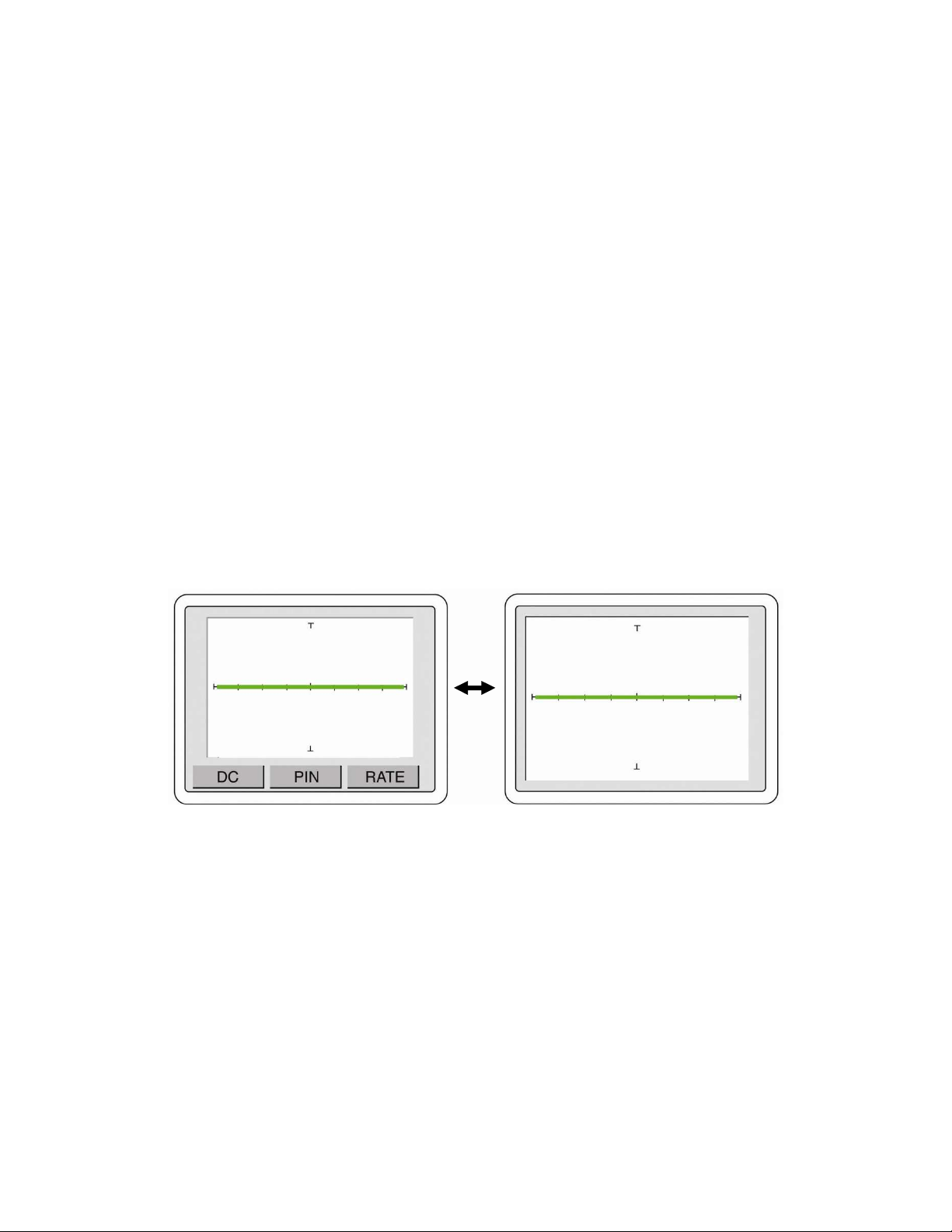
Shown in figure 2-19 are the factory default power-up menu (left image) and the full screen signature
screen mode (right image). Touch the signature portion of the screen to toggle between these two
screens.
Figure 2-19 Default Power-up screen (left) and Full Screen Signature mode (right)
DC Voltage Source Menus
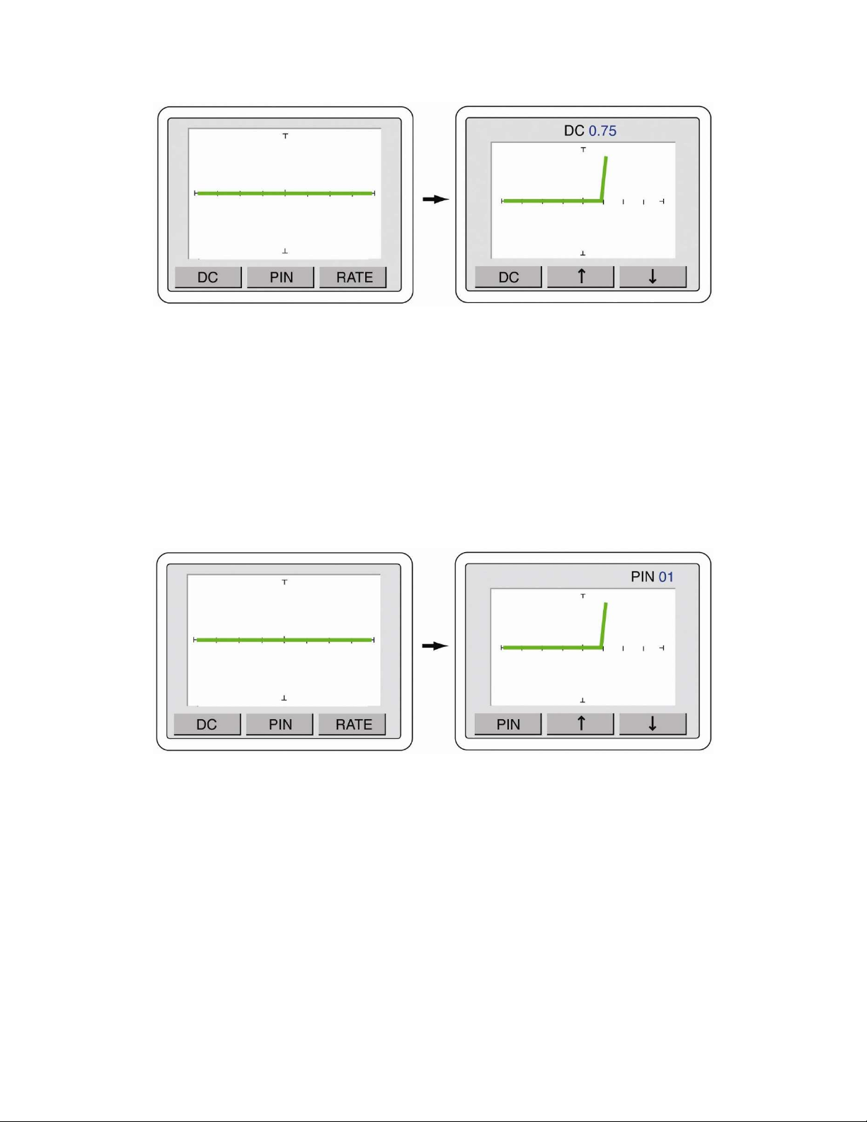
Control of the DC Voltage Source is accessed using the DC button on the touch screen power-up
menu. Press the DC button to display the DC Voltage Source controls as shown in figure 2-20. Use the
and arrow buttons to increase or decrease the voltage output from the DC Voltage source
connection (labeled “DC”) on the Tracker front panel. The voltage level will be displayed in the top
portion of the screen. The voltage can be adjusted in 0.25V increments.
Press the center signature area of the LCD touch screen to change the LCD to Full Screen Signature mode
28
Figure 2-20 DC Voltage Source menu controls
Press the DC button to return to the power-up screen.
PIN Controls (Tracker 2800S)
Stepping through individual pins with the Tracker 2800S is accomplished using the touch screen PIN
controls. Press the PIN button on the power-up menu to display the Pin controls as shown in figure 2-
21. Use the and arrow buttons to step through the component pins. The pin number will be
displayed in the top portion of the screen.
Figure 2-21 PIN menu controls
Press the PIN button to return to the power-up screen.
RATE (Alternate Speed) Controls
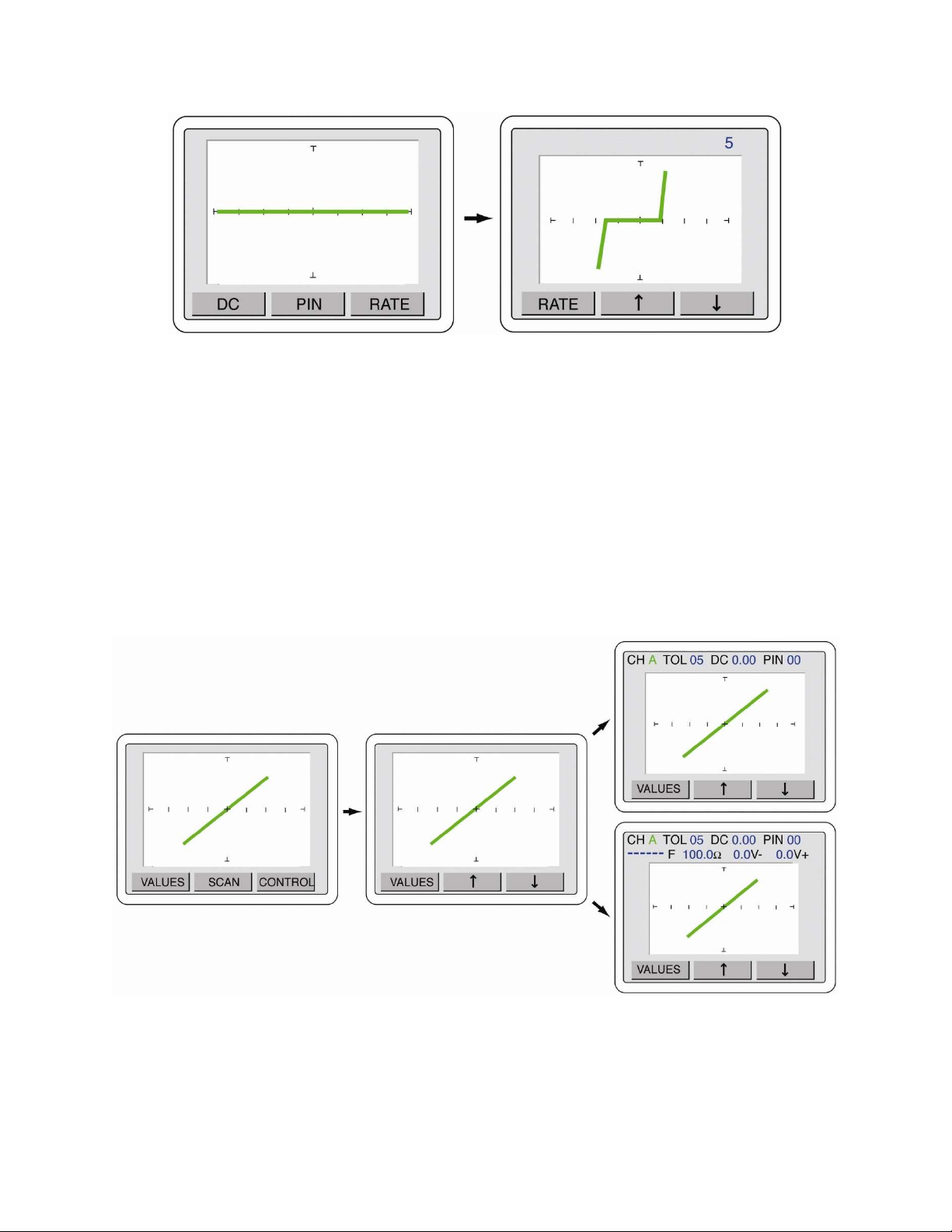
The speed of the Alternation (ALT) mode when comparing channel A versus Channel B is controlled
with the RATE controls. Press the RATE button to display the RATE controls menu as shown in
figure 2-22. Use the and arrow buttons to increase (lower number) or decrease (higher number –
up to 10) the alternation speed. ALT mode must be activated by pressing the ALT button on the
Tracker front panel.
29
Figure 2-22 RATE Controls menu
Press the RATE button to return to the power-up menu.
VALUES Controls
The VALUES function allows you display on-screen parameters such as channel, tolerance, DC
Voltage level and pin number (2800S) plus SigAssist values such as capacitance value, resistance
value, forward breakdown voltage and reverse breakdown voltage.
To access the VALUES menu controls, press the front panel MENU button to display the Main menu
(left image in figure 2-23). Press the VALUES button on the touch screen to display the VALUES
menu (middle image in figure 2-23). Use the and arrow buttons to toggle the values displayed on
the LCD (right images in figure 2-23). Note that the signature portion of the screen will become
smaller as additional values are displayed.
Figure 2-23 VALUES Control menus
Press the VALUES button to return to the Main menu or press the MENU front panel button twice to
return to the power-up menu.