Tracker-2800-2800S.pdf - 第81页
81 5-2. ANALOG CIRCU ITS Analog components and circuits represe nt another famil y of integrated circuit component s and include operational amplifiers (op amps), c omparators, references, regulators, ti mers and man y o…

80
REVIEW
Integrated circuits are complex devices that are built using basic electronic components.
The IC signatures resemble zener diodes.
There are many causes for IC failures and the Tracker 2800 can display its "health" as resistive
leakage, an open or a short.
Functionally identical pins on a single IC out-of-circuit will display the same signature.
The most common point for reference is ground, but V
CC
or another point might give a more
informative signature.
Different logic families exhibit different characteristic signatures.
Applications
Testing for faulty IC’s is one of the more common uses for the Tracker. A technician can compare IC’s
in or out of circuit.

81
5-2. ANALOG CIRCUITS
Analog components and circuits represent another family of integrated circuit components and include
operational amplifiers (op amps), comparators, references, regulators, timers and many other
specialized functions. These components and circuits present more troubleshooting challenges that are
unique to this particular family of ICs.
OP Amps
Frequently, each pin of an op amp creates a different signature on the Tracker 2800. This signature is
the result of the internal design of the chip and both the internal and external circuit elements
connected to it. This type of analog component typically has many internal junctions connected to each
pin and each pin may also be connected to numerous external components.
The following example will demonstrate ASA with a commonly used 741 type op amp. In this case it
is configured as an inverting amplifier circuit as in the schematic below.
Figure 5-9. Op Amp Symbol and Schematic Diagram of an Inverter Circuit.
We will examine the signatures of this analog IC and present some troubleshooting concepts for this
type of component.
OP Amp Signatures
Do the following to display the analog signatures of an op amp:
1. Select the 1K, 15V, 60Hz.
2. Place or clip the black test lead from the Tracker 2800's Common jack to the IC's ground or a
power supply pin. For this example, the negative power supply pin of the 741 is pin 4 and the
positive power supply is pin 8.
3. Use the red test lead from the Tracker 2800's Signal jack and probe each pin of the IC.
4. Observe that the signatures of each of the op amp's pins are unique.
82
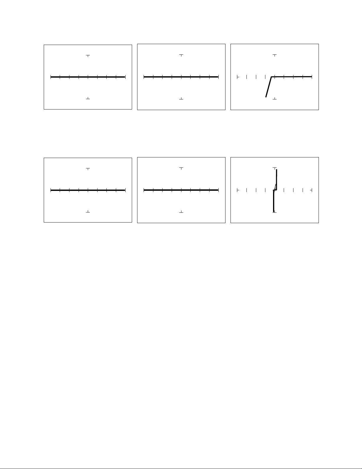
Pin 2 –Input Pin 3 +Input Pin 6 Output
Figure 5-10. Signatures of an Op Amp (741) at 10V, 50, 60Hz with Common to Pin 4.
Pin 2 -Input Pin 3 +Input Pin 6 Output
Figure 5-11. Signatures of an Op Amp (741) at 20V, 10K, 60Hz with Common to Pin 4.
Troubleshooting OP Amp Circuits
Troubleshooting an op amp in-circuit may be very challenging. These circuits usually have numerous
connections that act as feedback or compensation loops. This results in almost an infinite number of
possible analog signatures. Use the comparison test method when troubleshooting op amps in-circuit.
In this case, components on a suspect board are compared to those on a known good board. The
Tracker 2800 can help locate the defective component quickly.
The op amp has three main terminals; + input, - input and output. An alternative way to perform ASA
on the op amp is to connect Tracker 2800's Common terminal to the op amp's output while making a
comparison with the red test probe to the “ + ” and then the “ - ” leg. This eliminates problems
encountered when probing op-amps that are isolated from power and common. When there is more
than one op amp in a package, compare one with the other. The dual op amp and quad op amps are
very common. This technique also works with comparators.