Tracker-2800-2800S.pdf - 第54页
54 Review The switch has internal re sistance. As the test signal's volta ge decreases with each range change, the volts per d ivision of the horizontal ax is also decreases so that its analog signature becomes …
53
3-4. ELECTROMECHANICAL SWITCHING COMPONENTS
Switches are electrical devices that either stop or allow current to flow in a circuit. They are either in
an on or off state. Switching devices come in all types and sizes. There are simple mechanical
switches, relays, optical switches, and many kinds of semiconductor switches. They are different
because each uses a different kind of stimulus to turn them on or off. Because there are so many kinds
of switching devices, there is no single testing procedure that will test them all completely. With the
Tracker 2800, the test signal can be setup so that the switch's analog signature will verify its switching
function. The goal of this section is to develop a test strategy using ASA to test the switching function.
This is not a complete test, but it will be enough to determine whether or not the device is functioning
as a switch.
Manually Operated Mechanical Switches
A mechanical switch has two states: it is either open or closed. When open, no current can flow; when
closed, it acts as a short and allows current to flow. The Tracker 2800 can test the switching function
of mechanically activated switches easily. Unlike the DVM that samples and gives a continuity
measurement, the Tracker 2800 displays real time activity so if a switch has noisy, resistive or
intermittent operation, its analog signature on Tracker 2800's display will reflect these conditions.
Plug the red test microprobe in the Channel A jack, and the black test clip lead in the Common jack.
Do the following to display the analog signature of a mechanical switch:
1. Select the V
S
= 10 V, R
S
= 50, F
S
= 60Hz range button.
2. Place or clip each test lead to the switch leads and observe its signature on the Tracker 2800
signature display.
3. Turn the switch to it’s on or off position.
10K 1K 50
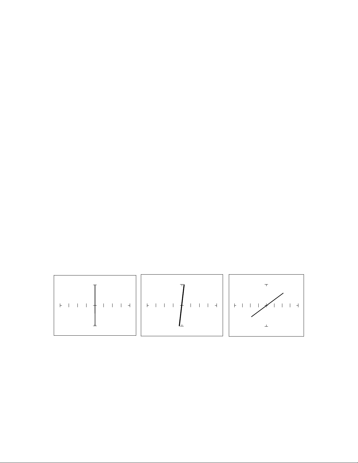
Figure 3-23. Signatures of a pressed Keyboard Pushbutton Conductive Elastomer Switch.
Note that as the ranges change from 10Kto1Kto 50, the signature tilts away from the vertical.
This characteristic is similar to other components with internal resistance.
54
Review
The switch has internal resistance.
As the test signal's voltage decreases with each range change, the volts per division of the
horizontal axis also decreases so that its analog signature becomes more pronounced. This is
caused by the small voltage drop across the switch's internal resistance.
Electromechanical Switches
A relay is a switch that's activated by an electrical control input. The relay consists of switch contacts,
magnets and an electromagnetic coil. The Tracker 2800 can test the coil part of the relay by looking at
its inductive analog signature.
Relay Coil Test
Do the following:
1. Select the V
S
= 10V, R
S
= 50, F
S
= 2KHz range.
2. Connect the black test lead from Tracker 2800’s Common jack to one side the relay coil (normally,
the minus lead).
3. Connect the red test lead from Tracker 2800’s Signal jack to the other side of the relay coil
(normally, the plus lead).
Observe the analog signatures of a magnetic reed type relay in the following figure.
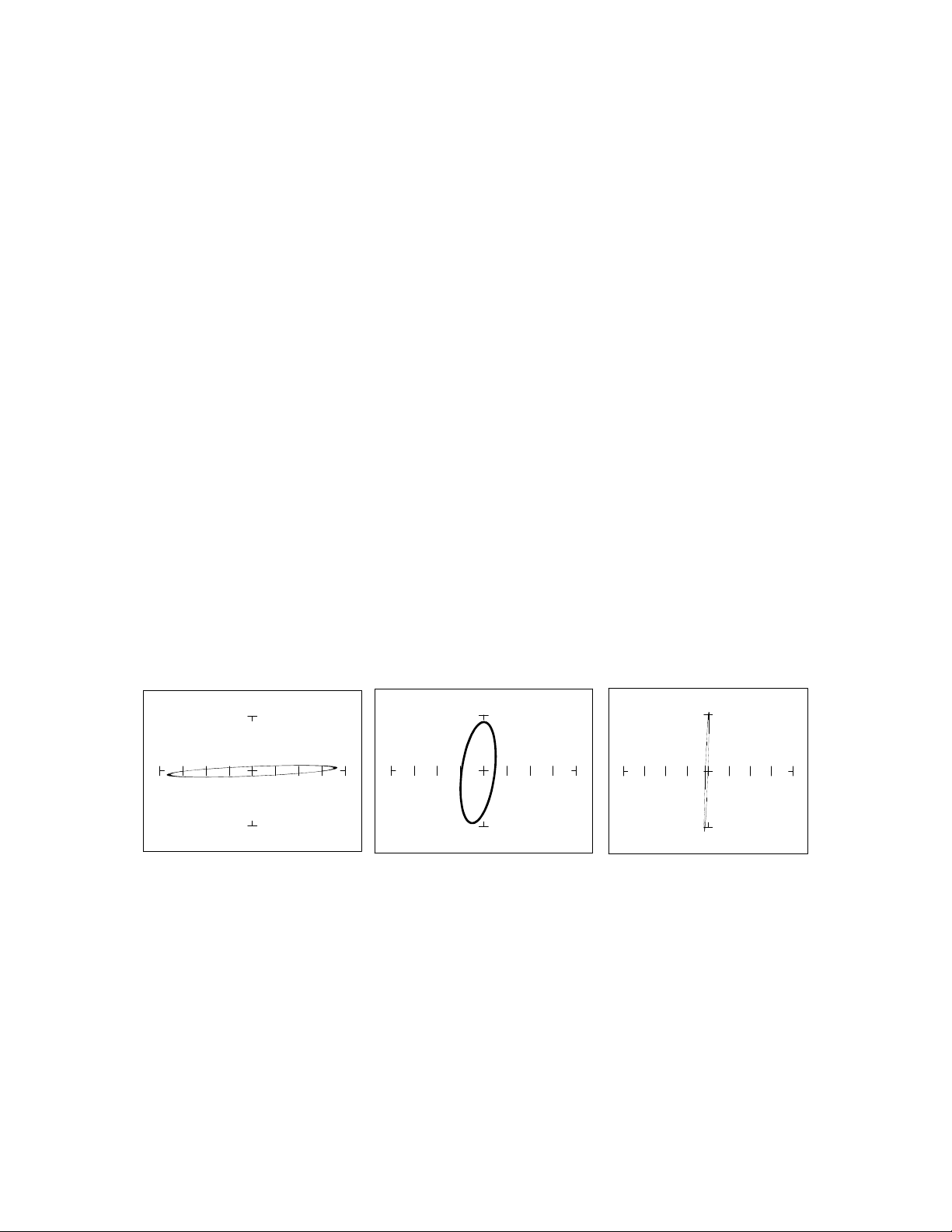
50 1K 20K
Figure 3-24. Signatures of a Magnetic Reed Relay Coil at 2KHz.
Note the characteristic inductive oval at 3 resistances. When applying Tracker 2800’s test signal to the
coil, there may be an audible ringing sound generated from the relay under test from the switch
contacts being excited.
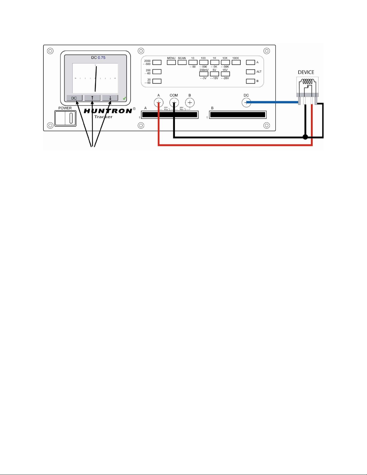
To test the contacts of a relay, use the Tracker to monitor the relay contacts while applying voltage to
the relay coil using the Tracker 2800 DC Voltage Source.
55
Figure 3-25. Using the Tracker 2800 DC Voltage Source for Relay Testing
Review
The Tracker 2800 can test switches in real time. This makes an excellent test for microswitches,
power switches, control switches, pressure and heat sensor switches.
As the mechanical switch closes, watch for erratic or discontinuous signature. Switch bounce will
display as multiple closure signatures. Resistive contacts will display a resistive signature at 50.
Use the arrow buttons to increase/decrease
voltage level applied to relay