Tracker-2800-2800S.pdf - 第55页
55 Figure 3-25 . Using the Tra cker 2800 DC Voltage Source for Rel ay Testing Review The Tracker 2800 can test s witches in real time. This ma kes an excellent test for microswitche s, power switches, control swi tches…
54
Review
The switch has internal resistance.
As the test signal's voltage decreases with each range change, the volts per division of the
horizontal axis also decreases so that its analog signature becomes more pronounced. This is
caused by the small voltage drop across the switch's internal resistance.
Electromechanical Switches
A relay is a switch that's activated by an electrical control input. The relay consists of switch contacts,
magnets and an electromagnetic coil. The Tracker 2800 can test the coil part of the relay by looking at
its inductive analog signature.
Relay Coil Test
Do the following:
1. Select the V
S
= 10V, R
S
= 50, F
S
= 2KHz range.
2. Connect the black test lead from Tracker 2800’s Common jack to one side the relay coil (normally,
the minus lead).
3. Connect the red test lead from Tracker 2800’s Signal jack to the other side of the relay coil
(normally, the plus lead).
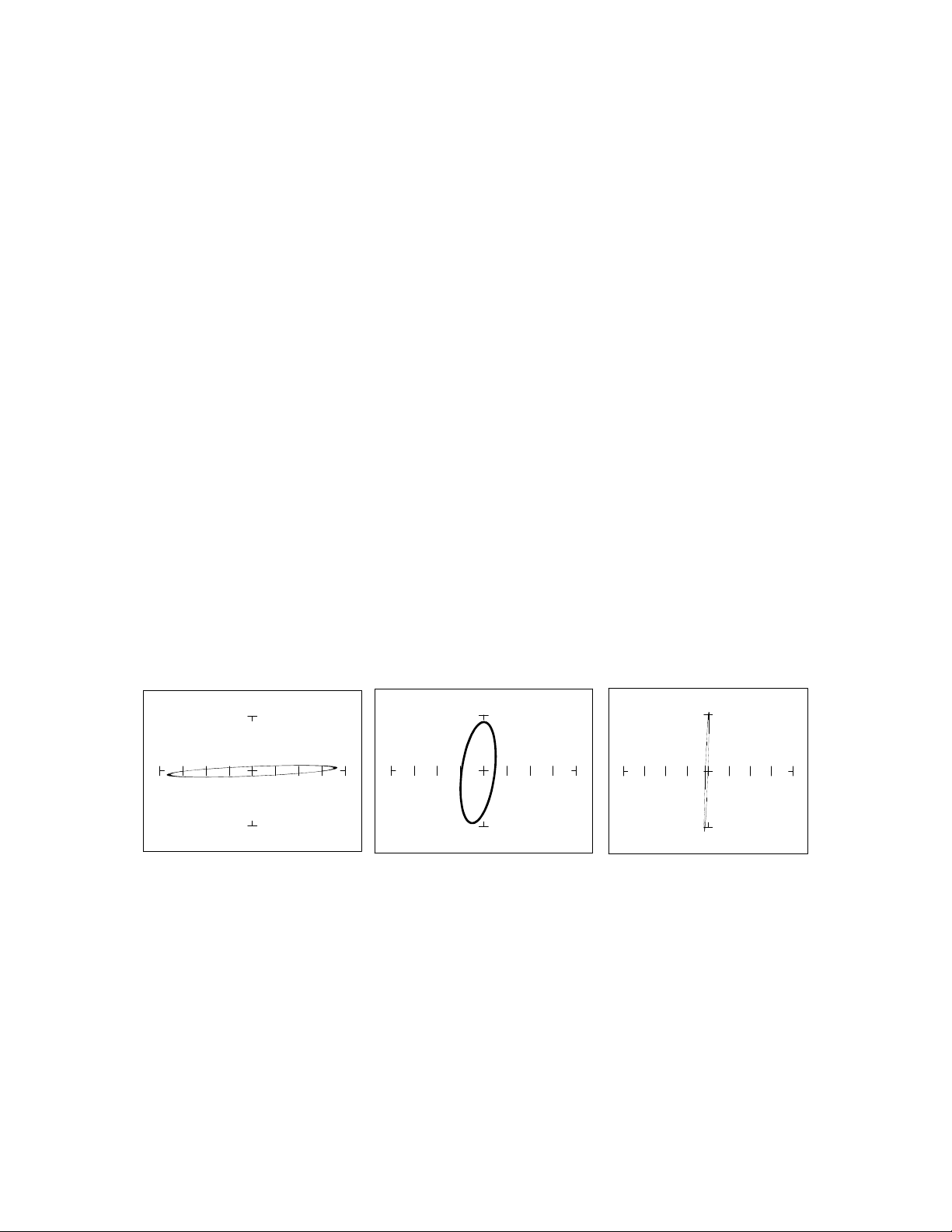
Observe the analog signatures of a magnetic reed type relay in the following figure.
50 1K 20K
Figure 3-24. Signatures of a Magnetic Reed Relay Coil at 2KHz.
Note the characteristic inductive oval at 3 resistances. When applying Tracker 2800’s test signal to the
coil, there may be an audible ringing sound generated from the relay under test from the switch
contacts being excited.
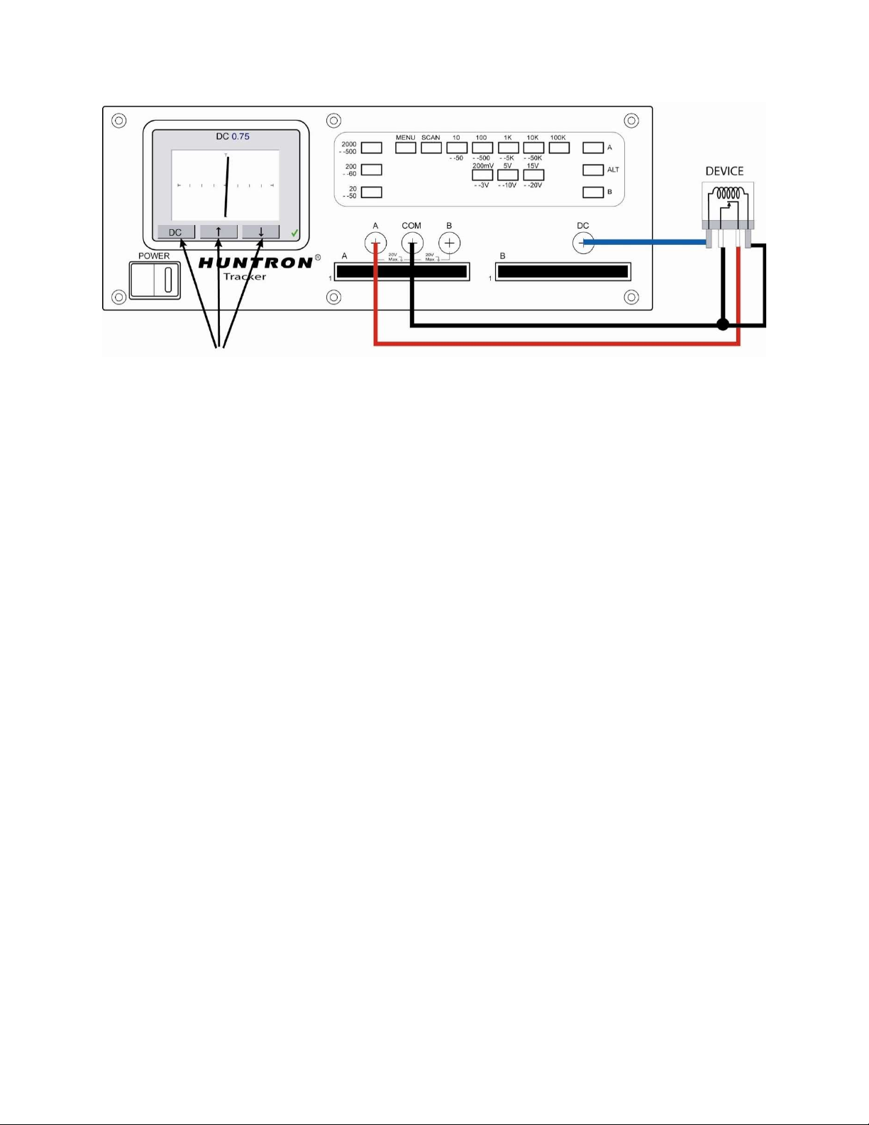
To test the contacts of a relay, use the Tracker to monitor the relay contacts while applying voltage to
the relay coil using the Tracker 2800 DC Voltage Source.
55
Figure 3-25. Using the Tracker 2800 DC Voltage Source for Relay Testing
Review
The Tracker 2800 can test switches in real time. This makes an excellent test for microswitches,
power switches, control switches, pressure and heat sensor switches.
As the mechanical switch closes, watch for erratic or discontinuous signature. Switch bounce will
display as multiple closure signatures. Resistive contacts will display a resistive signature at 50.
Use the arrow buttons to increase/decrease
voltage level applied to relay
56
SECTION 4 TESTING DISCRETE SEMICONDUCTORS
4-1. DIODES
The most basic type of solid state semiconductor component is the diode. Diodes are formed by
creating a junction between p-type and n-type semiconductor material. The pn junction gives diodes
and semiconductor components polarity characteristics that allow them to conduct current when an
external voltage is applied. They conduct current in one direction, but not in the other. Current flows in
a diode when the positive terminal (anode) is made more positive than the negative terminal (cathode).
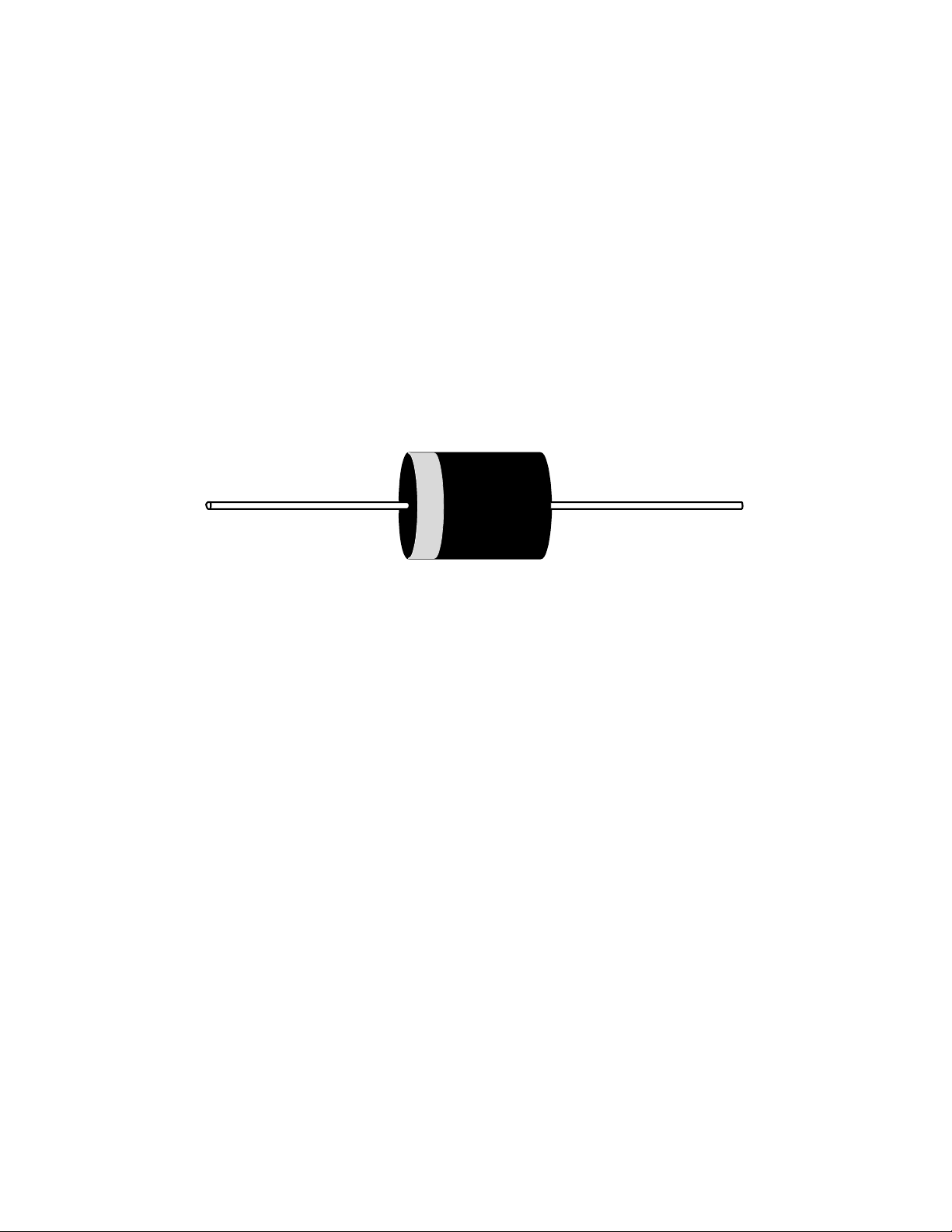
Figure 4-1 shows how the diode symbol indicates the polarity of the diode.
Figure 4-1. Diode and Schematic Symbol.
Diode Signatures
Diode signatures demonstrate the fundamental operation of a semiconductor junction. There is a
threshold or forward voltage V
F
(about 0.6V for a silicon diode) at which the diode begins to conduct
current. The diode acts as an open circuit and no current flows as long as the voltage differential
between the anode and cathode is below that threshold. As the anode to cathode voltage becomes more
positive, the diode will begin to conduct current. Once current begins to flow in the diode, very small
increases in anode voltage will cause very large increases in current. In analog signature analysis, this
is called the “knee” effect in which is characteristic of a good semiconductor junction.