Tracker-2800-2800S.pdf - 第39页
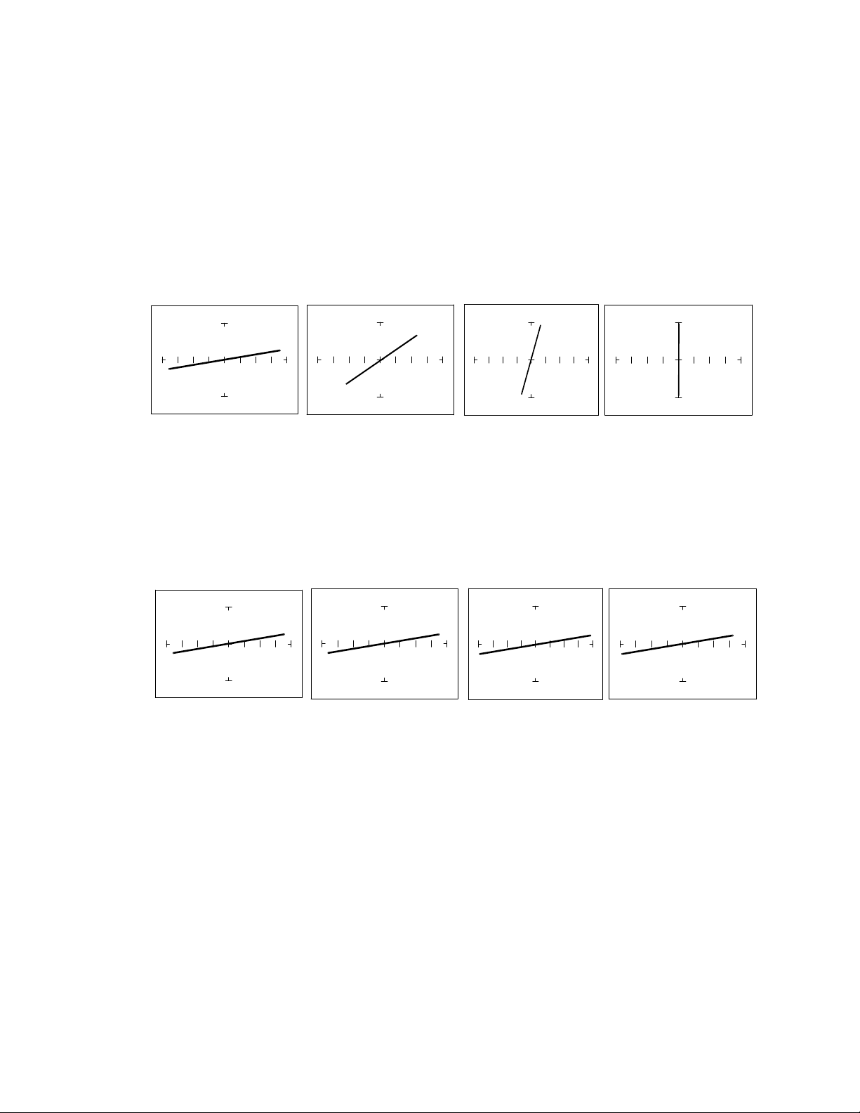
39 The Effect of F S on Resistor Analog Sig natures. Select the 10V, 50 and 20Hz range. Change the Frequenc y to 60Hz, 1KHz and 2KHz. Observe the resistor signatures in the followi ng figures do not change as F S chang…
38
Now that you have an idea of what the signatures of different resistor values look like in different
ranges, the next part will give you an idea of what happens when you vary R
S
source resistance, V
S
source voltage and F
S
source frequency of the Tracker 2800 and how it affects the resistive analog
signature.
The Effect of R
S
on Resistor Analog Signatures.
Select the 10V, 50 and 200Hz. Change the resistance range to 200, 1K and 5K.
Observe the signatures for a 100 ohm resistor in the figure below as R
S
varies. Note how these resistor
signatures respond to changing Tracker 2800's internal resistance.
R
S
= 50 R
S
= 100 R
S
= 1K R
S
= 10K
Figure 3-3. Effect of Varying R
S
on a 100Resistor Signature
The Effect of V
S
on Resistor Analog Signatures.
Select the 10V, 50 and 200Hz. Change the voltage range to 5V, 2V and 200mV.
V
S
= 10V V
S
= 5V V
S
= 2V V
S
= 500mV
Figure 3-4. Effect of Varying V
S
on a 100 Resistor Signature.
Observe that these signatures do not change with the changing voltage. Note that Vs cannot be set
above 10V because R
S
is set to a value of 50 . This limit on range parameter combinations is a result
of the Tracker 2800's STAR feature. It protects components from possible excessive power levels. In
order to set V
S
to a higher voltage, you must change R
S
to a higher value first.
39
The Effect of F
S
on Resistor Analog Signatures.
Select the 10V, 50 and 20Hz range. Change the Frequency to 60Hz, 1KHz and 2KHz. Observe the
resistor signatures in the following figures do not change as F
S
changes.
Fs = 20 Hz Fs = 60 Hz Fs = 1KHz Fs = 2KHz
Figure 3-5. Effect of Varying F
S
on a 100Resistor Signature.
Shorts, Opens and Resistor Faults
Two of the most common faults that occur in electronic components and circuits are shorts and opens.
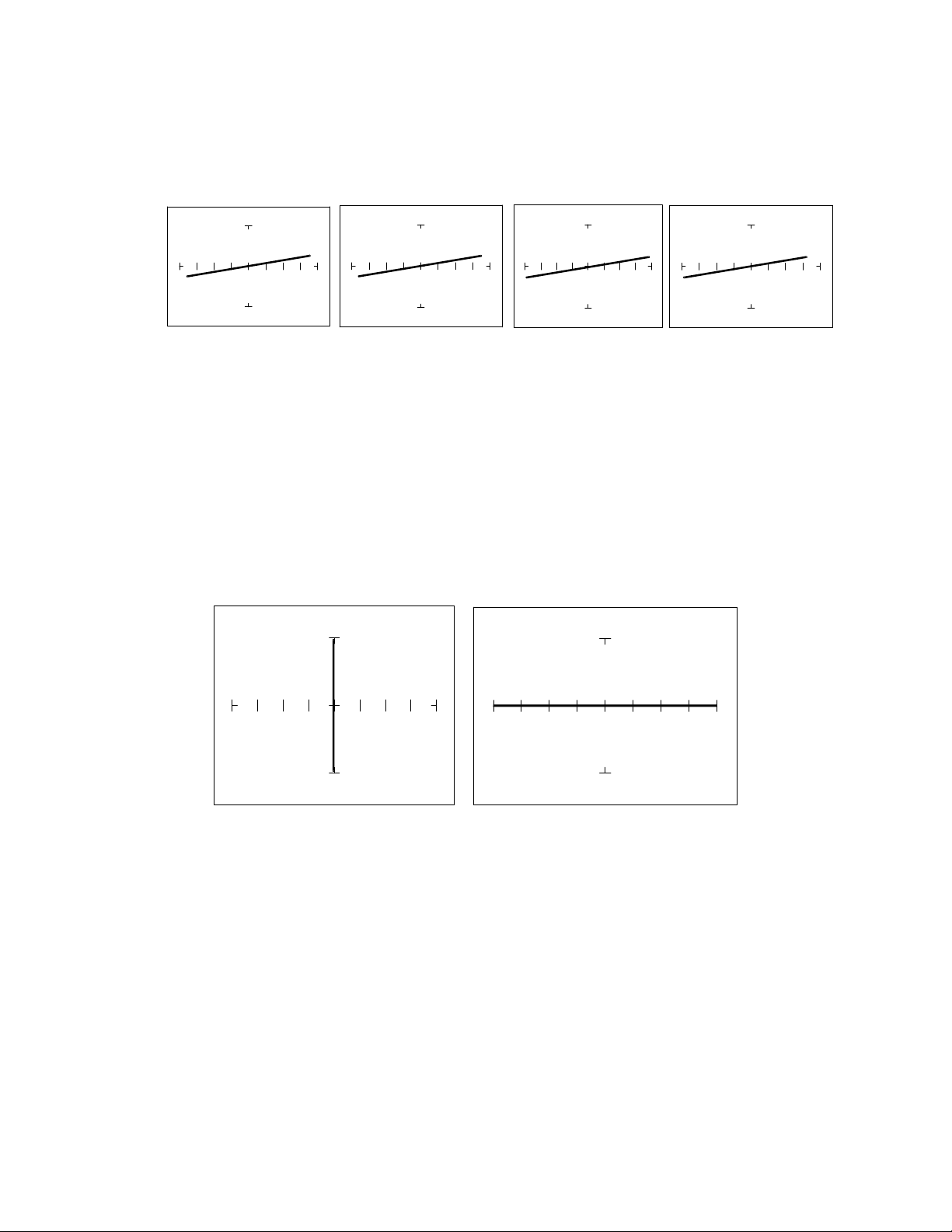
A short circuit is typically a 0 to 10 low resistive path between two points in a component or
circuit that normally would have a higher resistance between them. An open circuit is a break between
two points in a component or circuit that prevents current from flowing.
Short Open
Figure 3-6. Short and Open Signature.

40
Review
The signature of a purely resistive circuit is a straight line because the relationship between voltage
and current in a purely resistive circuit is linear.
This straight line signature can vary from
completely horizontal (an open)
completely vertical ( a short)
As resistance increases
current decreases
the signature becomes more horizontal
As the range increases
the volts per division of the horizontal axis increases
the internal resistance increases
the signature becomes more vertical
Troubleshooting Applications
The Tracker 2800 is a fast and efficient continuity tester, providing real time information.
The Tracker 2800 will quickly locate resistor defects, shorts, opens and degradation that other
testers cannot find.
A majority of component failures are resistive in nature. This is important to remember; a
component fault may only appear in one range because of the resistive nature of the fault.
The Tracker 2800’s ability to determine the approximate fault resistance value greatly enhances the
troubleshooting capability if the correct value is known.
The Tracker 2800 can be used to adjust a potentiometer in circuit to an approximate operational
setting. This application requires a known good board. Adjust each potentiometer on the board
under repair to match the settings on a known good operational board. In most cases, the board
under repair can now be powered up to an operational state where it can be adjusted to true
specifications.