Tracker-2800-2800S.pdf - 第29页
29 Figure 2-22 RATE Controls m enu Press the RATE butto n to return to the power-up menu. V ALUES Controls The VALUES function allo ws you display on-screen parameter s such as channel, tolerance, DC Voltage level and pi…
28
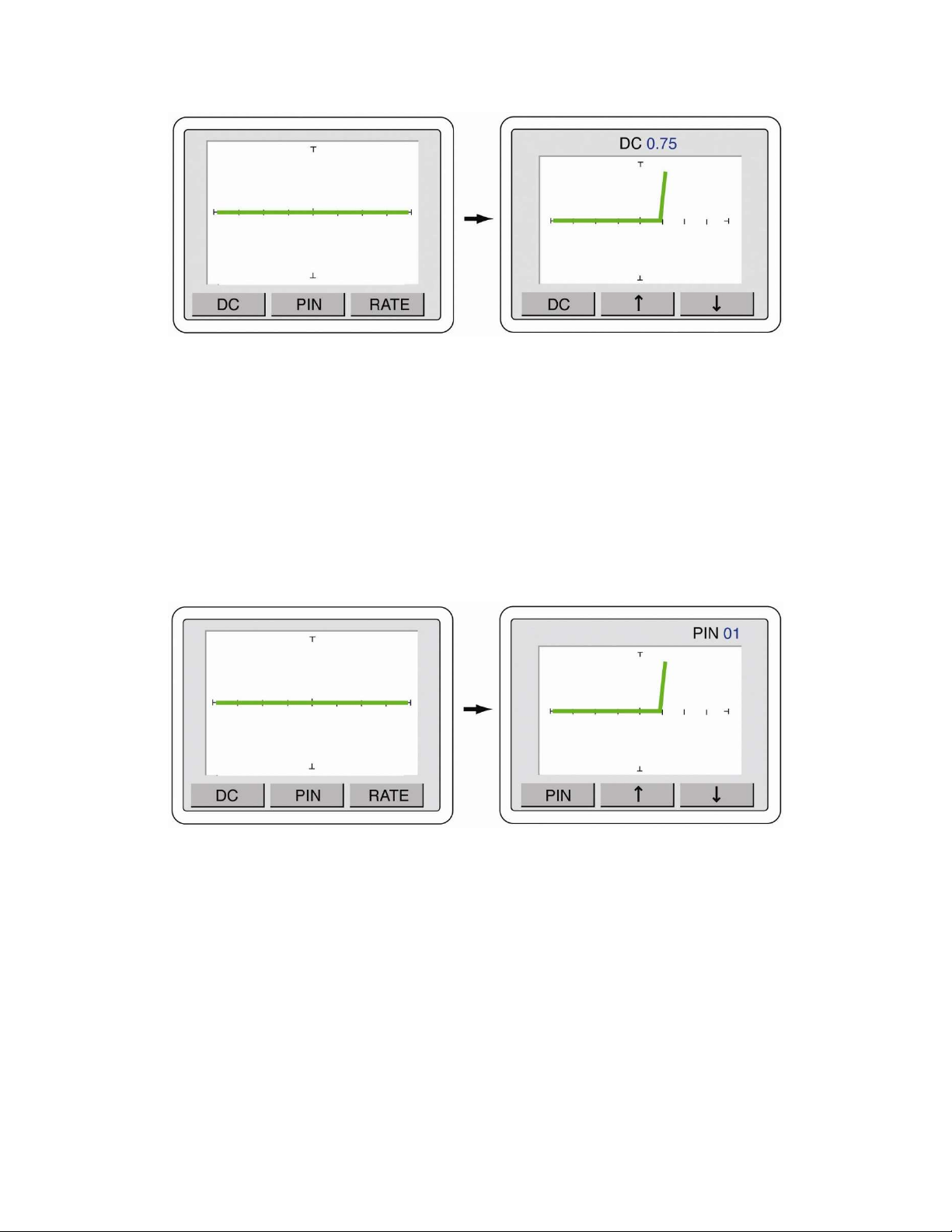
Figure 2-20 DC Voltage Source menu controls
Press the DC button to return to the power-up screen.
PIN Controls (Tracker 2800S)
Stepping through individual pins with the Tracker 2800S is accomplished using the touch screen PIN
controls. Press the PIN button on the power-up menu to display the Pin controls as shown in figure 2-
21. Use the and arrow buttons to step through the component pins. The pin number will be
displayed in the top portion of the screen.
Figure 2-21 PIN menu controls
Press the PIN button to return to the power-up screen.
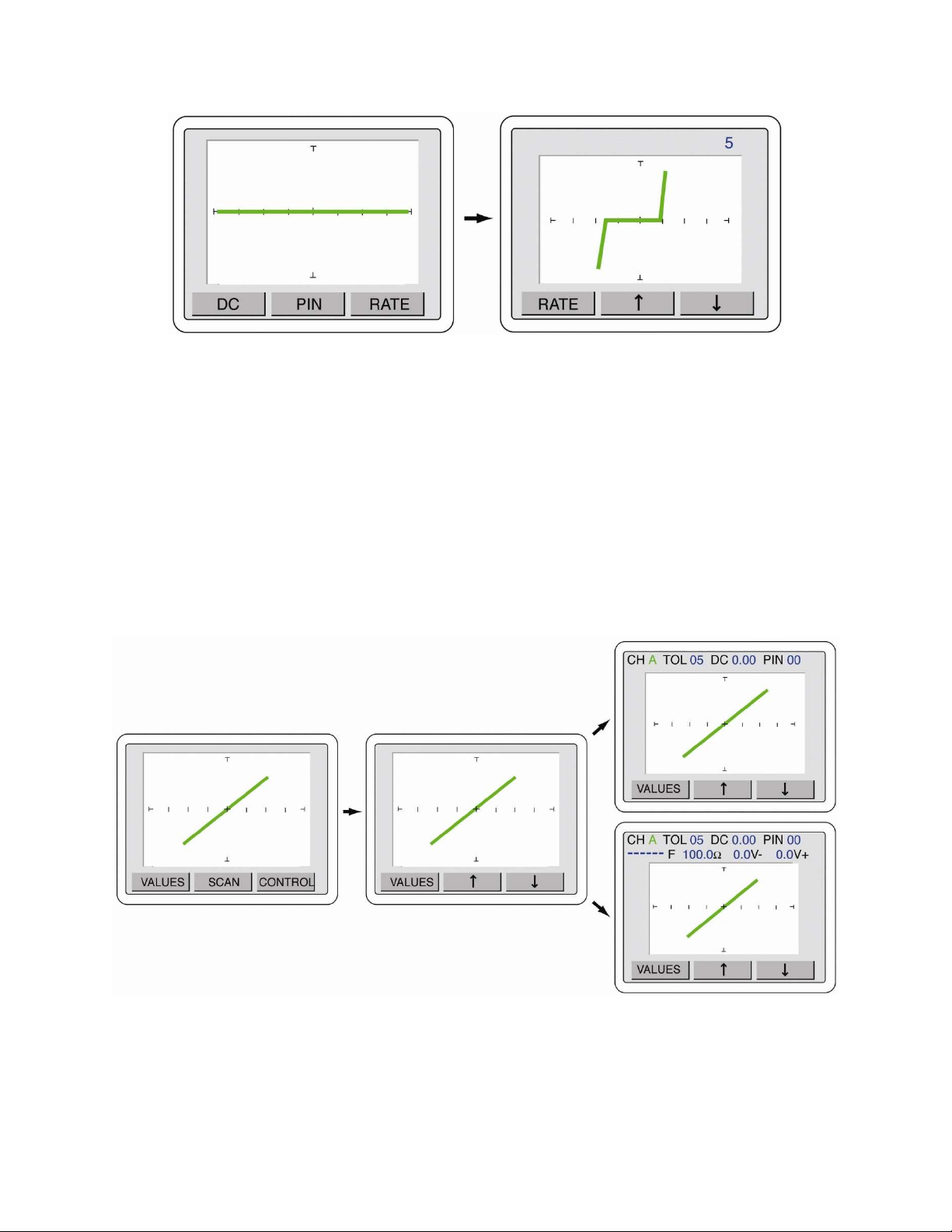
RATE (Alternate Speed) Controls
The speed of the Alternation (ALT) mode when comparing channel A versus Channel B is controlled
with the RATE controls. Press the RATE button to display the RATE controls menu as shown in
figure 2-22. Use the and arrow buttons to increase (lower number) or decrease (higher number –
up to 10) the alternation speed. ALT mode must be activated by pressing the ALT button on the
Tracker front panel.
29
Figure 2-22 RATE Controls menu
Press the RATE button to return to the power-up menu.
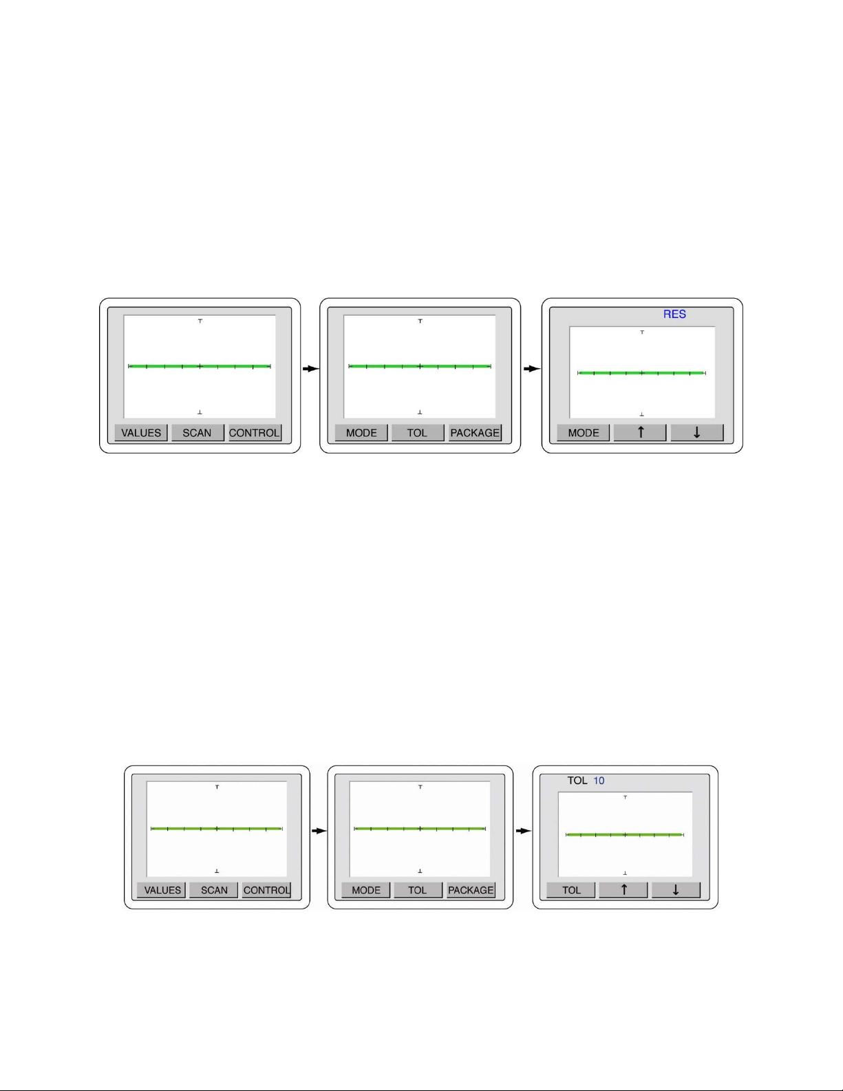
VALUES Controls
The VALUES function allows you display on-screen parameters such as channel, tolerance, DC
Voltage level and pin number (2800S) plus SigAssist values such as capacitance value, resistance
value, forward breakdown voltage and reverse breakdown voltage.
To access the VALUES menu controls, press the front panel MENU button to display the Main menu
(left image in figure 2-23). Press the VALUES button on the touch screen to display the VALUES
menu (middle image in figure 2-23). Use the and arrow buttons to toggle the values displayed on
the LCD (right images in figure 2-23). Note that the signature portion of the screen will become
smaller as additional values are displayed.
Figure 2-23 VALUES Control menus
Press the VALUES button to return to the Main menu or press the MENU front panel button twice to
return to the power-up menu.
30
SCAN – MODE Controls
The SCAN – MODE controls how the Tracker will step through a selected range parameter when the
Scan mode is started by pressing the SCAN front panel button. The SCAN mode can step through
voltage (VOL), resistance (RES), frequency (FREQ) or NONE. To set the SCAN mode, press the
MENU front panel button to display the Main menu (left image in figure 2-24). Press the SCAN
button to display the SCAN menu (middle image in figure 2-24). Press the MODE button to display
the MODE menu (right image in figure 2-24). Use the and arrow buttons to step the selections of
voltage (VOLT), resistance (RES), frequency (FREQ) or NONE.
Figure 2-24 SCAN - MODE menus
Press the MENU front panel button three times to return to the power-up menu or press the MODE
button to go back to the SCAN menu. The range combinations used when scanning are controlled
within the Smart Tracker Active Range limits (see section 2-10).
SCAN – TOL (Tolerance) Controls
The SCAN – TOL controls the tolerance allows when the signature on channel A is compared against
the signature on channel B. The tolerance is adjustable from 0 to 90. The larger the tolerance, the
greater the two signatures can differ and still be considered a “pass” when compared against each
other. To access the SCAN – TOL control menus, press the MENU front panel button to display the
Main menu (left image in figure 2-25). Press the SCAN button to display the SCAN menu (middle
image in figure 2-25). Press the TOL button to display the MODE menu (right image in figure 2-25).
Use the and arrow buttons to adjust the tolerance value to the desired setting.
Figure 2-25 SCAN – TOL menus
It is recommended that a low setting such as 5 or 10 be used for general purpose comparison
troubleshooting.