Tracker-2800-2800S.pdf - 第26页
26 2-14 Using the O ptional Footswitch with th e Tracker 2800/2800S An optional footswitch (Huntron part number 98-0314) is available for controlling certain functions of the Tracker 2800. It connects to t he auxiliar y …
25
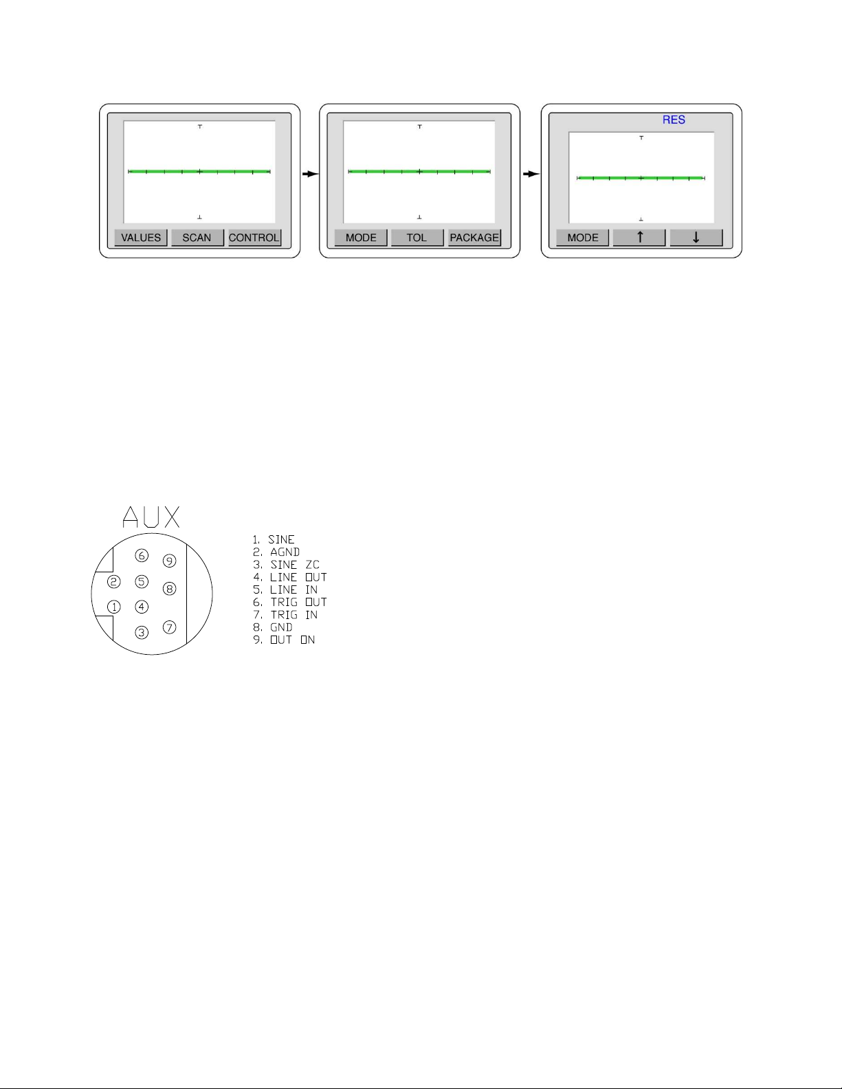
Figure 2-15. Selecting range parameter used while scanning
Press the MENU button until the power-up menu is reach (the signature will become live at this point).
Pressing the SCAN button will now scan through the component pins using the range parameter
selected in the Scan MODE menu.
2-13 Auxiliary (AUX) connector description
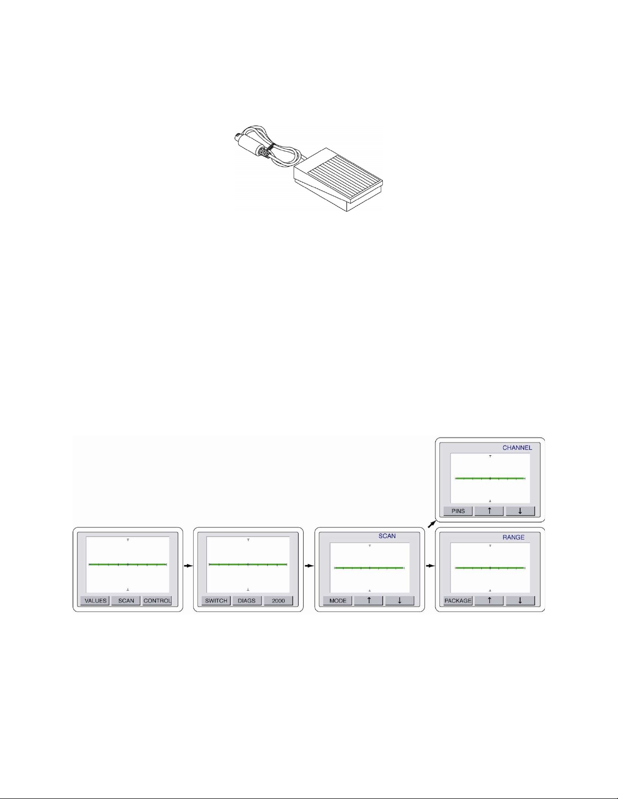
The rear panel Auxiliary (AUX) 9 pin Din connector pins are shown figure 2-16. This connection is
used for control of the Tracker with the optional footswitch accessory.
Press the SCAN button Press the MODE button Use and to select the Scan mode
Figure 2-16
Auxiliary connector pin out
diagram
26
2-14 Using the Optional Footswitch with the Tracker 2800/2800S
An optional footswitch (Huntron part number 98-0314) is available for controlling certain functions of
the Tracker 2800. It connects to the auxiliary port located on the Tracker back panel.
Figure 2-17
Footswitch accessory for Tracker 2800/2800S
The footswitch can be used for hands-free control of start/stop of scanning, changing the channel and
changing to a pre-selected range.
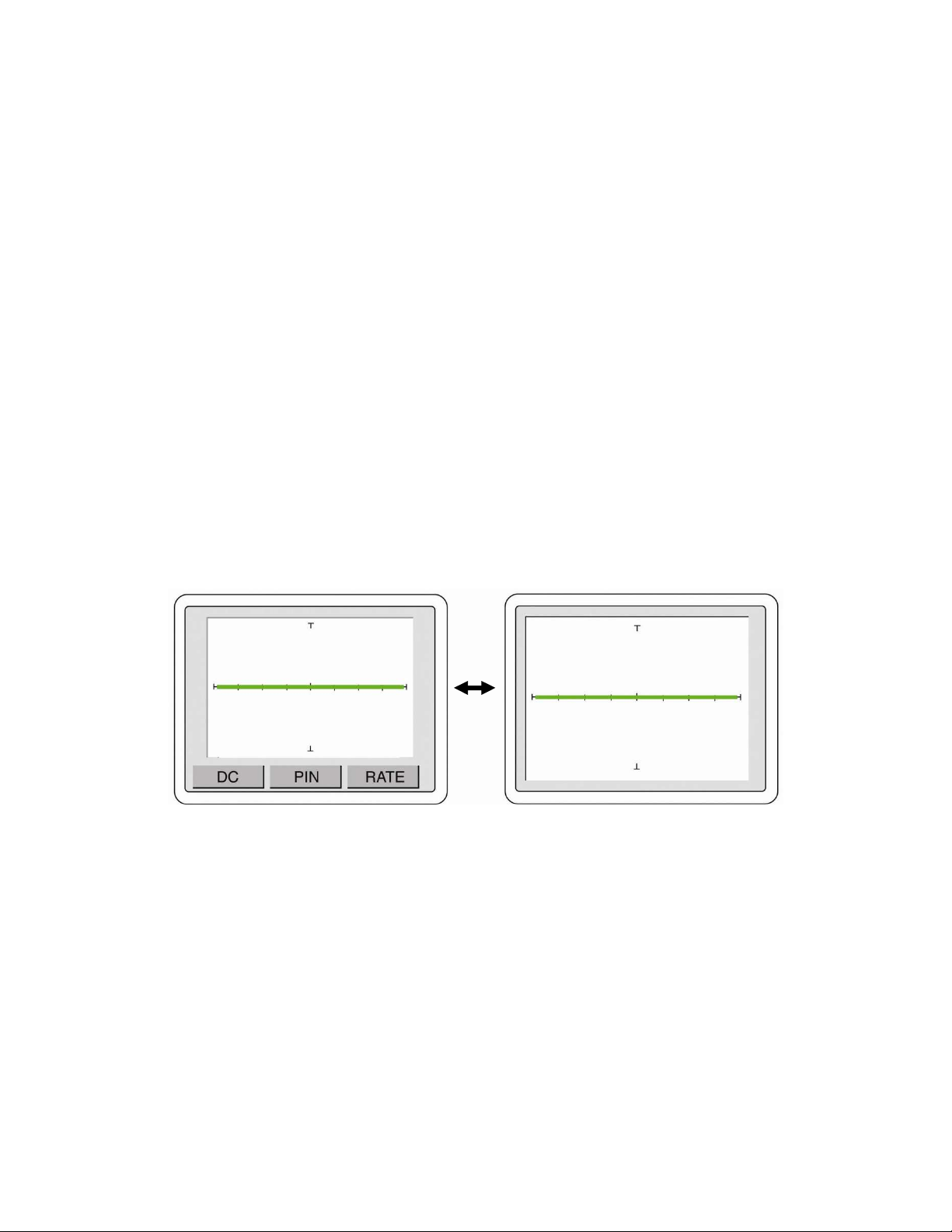
To configure the footswitch control press the front panel MENU button to display the Main menu on
the LCD (left image in figure 2-18). Press the CONTROL button on the LCD to display the Control
menu (image second from left in figure 2-18). Press the SWITCH button on the LCD to display the
Switch menu (image third from left in figure 2-18). Use the and arrow buttons to select the
footswitch control between SCAN (image third from left in figure 2-18), CHANNEL (middle image
on right in figure 2-18) and RANGE (bottom image on right in figure 2-18).
Figure 2-18 Tracker 2800 Footswitch Control Menus
Press the MODE button to return to the Control menu or press the front panel MENU continuously
until the power-up menu is displayed.
Press the CONTROL button Press the SWITCH button Use and to select the Switch mode
27
The footswitch controls work as follows:
SCAN: Pressing the footswitch will start and stop the SCAN mode (same as manually pressing
the front panel SCAN button).
CHANNEL: Pressing the footswitch will change the channel from A to B or vice versa.
RANGE: Pressing the footswitch will change to the range set when the mode is selected (i.e.,
set the range to 3V, 10K, 200Hz, select footswitch RANGE mode; pressing the footswitch
will automatically change the Tracker to this range). This is useful for changing to a favorite
range by simply pressing the footswitch.
2-15 Tracker 2800/2800S Touch Screen Menus
The Tracker 2800/2800S utilizes a color LCD touch screen menu system for configuring operation of
the Tracker 2800/2800S.
Default Power-up menu and Full Screen Signature mode
Shown in figure 2-19 are the factory default power-up menu (left image) and the full screen signature
screen mode (right image). Touch the signature portion of the screen to toggle between these two
screens.
Figure 2-19 Default Power-up screen (left) and Full Screen Signature mode (right)
DC Voltage Source Menus
Control of the DC Voltage Source is accessed using the DC button on the touch screen power-up
menu. Press the DC button to display the DC Voltage Source controls as shown in figure 2-20. Use the
and arrow buttons to increase or decrease the voltage output from the DC Voltage source
connection (labeled “DC”) on the Tracker front panel. The voltage level will be displayed in the top
portion of the screen. The voltage can be adjusted in 0.25V increments.
Press the center signature area of the LCD touch screen to change the LCD to Full Screen Signature mode