Tracker-2800-2800S.pdf - 第61页
61 Internal Resistance Fau lt in a Diode Figure 4-11 . Defective Diode Model w ith a Small Series Resisto r. 50 10V 1K 15V 20K , 20V Figure 4-12 . Defective Diode Signature with a 50 Series Resistor. The 50 r…
60
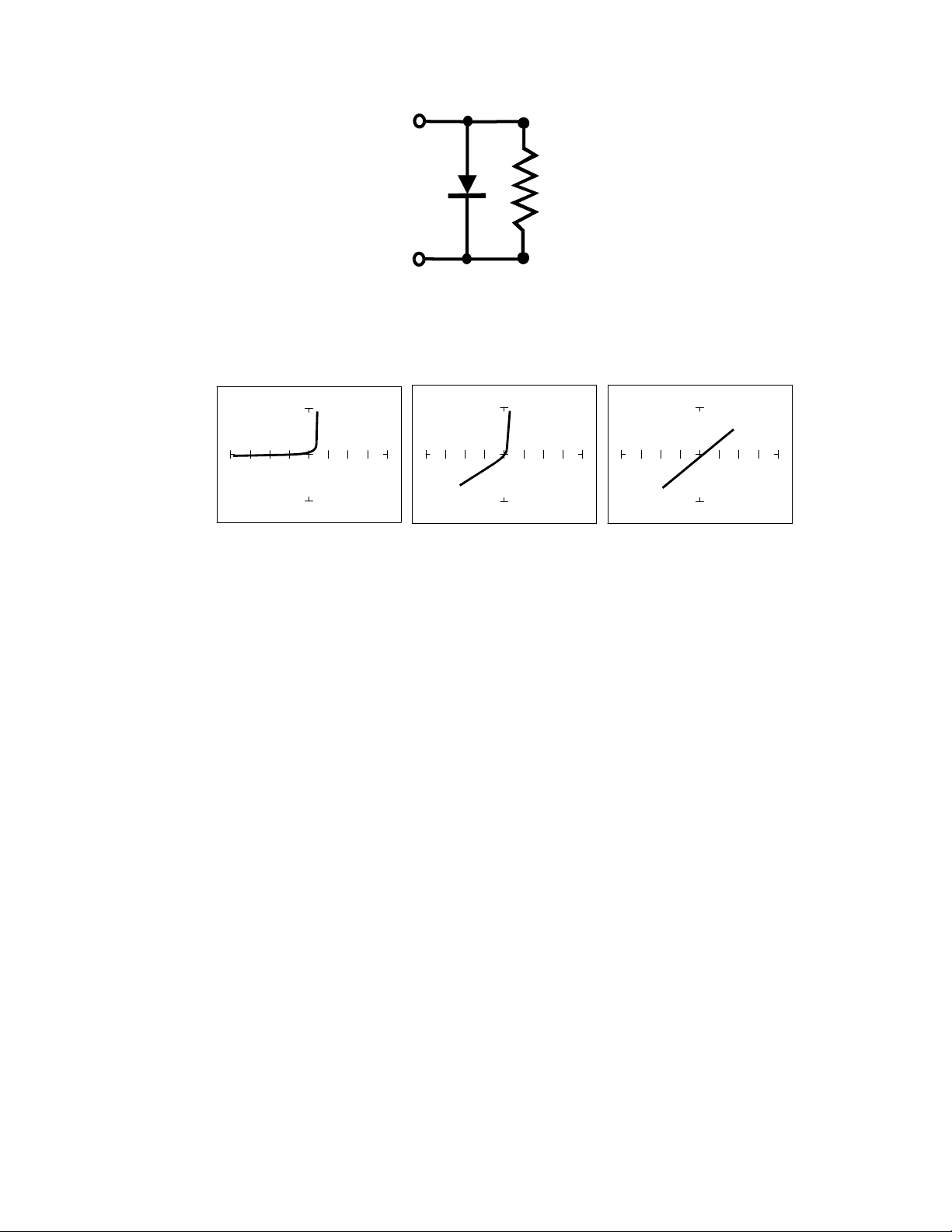
Figure 4-9. Composite Model of a Diode and Resistor in Parallel.
V
S
= 10 V, R
S
= 50 V
S
= 10 V, R
S
= 1K V
S
= 200 mV, R
S
= 1K
Figure 4-10. Composite Signature - 1N914 Diode and 1KResistor in Parallel.
The signature on the left shows only the diode signature because the test signal resistance is set below
any visible contribution due the 1k resistor. The composite signature in the center consists of the
distinctive slope of the resistor and the "knee" pattern of the diode. The signature on the right shows
only the resistor signature because the test signal voltage is below the diode's turn on level. Again,
when multiple components are connected together, it's important to realize that the Tracker 2800 has
the ability to selectively display the signature of a single component.
Diode Failures
Diodes can fail in a number of ways, and each type of failure will cause the signature to change. The
defective diodes often appear as open and short signatures. Two other types of flaws are internal
resistance and leakage.
61
Internal Resistance Fault in a Diode
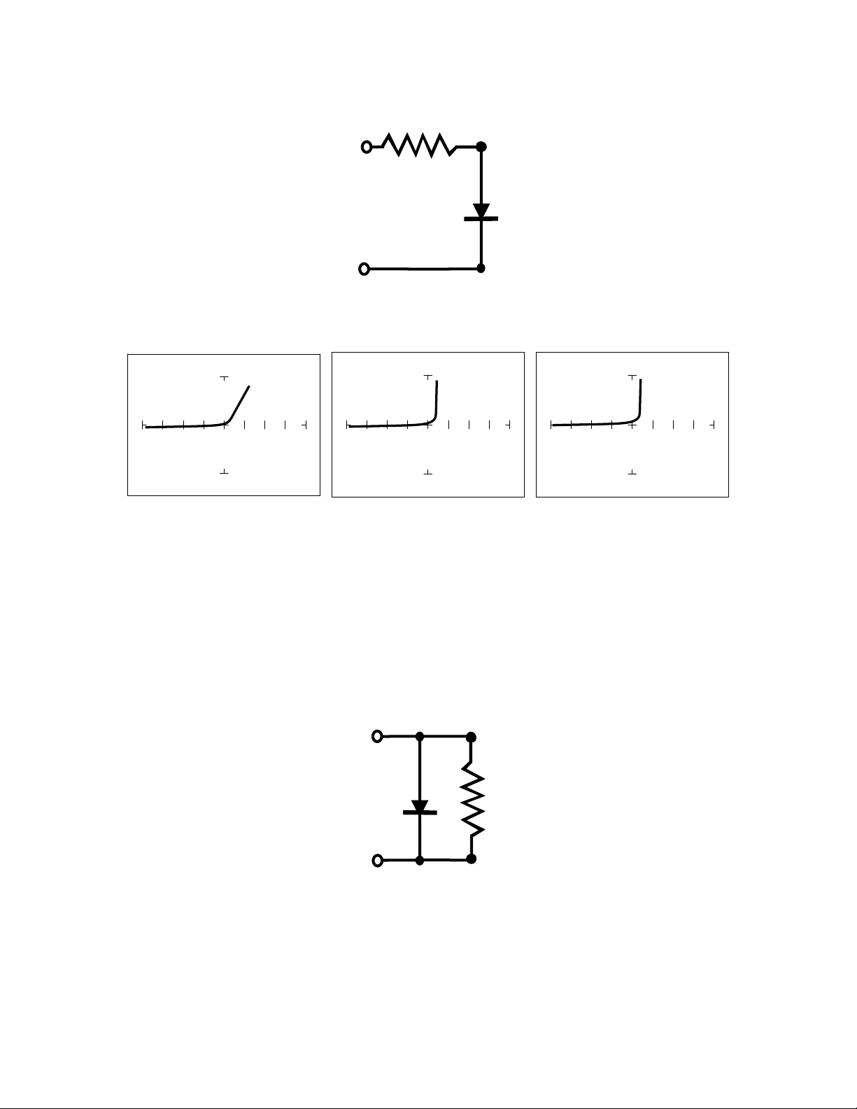
Figure 4-11. Defective Diode Model with a Small Series Resistor.
50 10V 1K 15V 20K, 20V
Figure 4-12. Defective Diode Signature with a 50 Series Resistor.
The 50 range shows that there is a resistive component to the signature when the diode is conducting.
This is the result of a defect in the diode's internal PN junction. The resistance is visible only in 50
range because the voltage drop across it is small. In the other two ranges, the resistance is masked due
to the internal resistances being too large to show such a small voltage drop.
Internal Leakage Fault in a Diode
Figure 4-13. Defective Diode Model with an Internal Leakage Resistance.
62
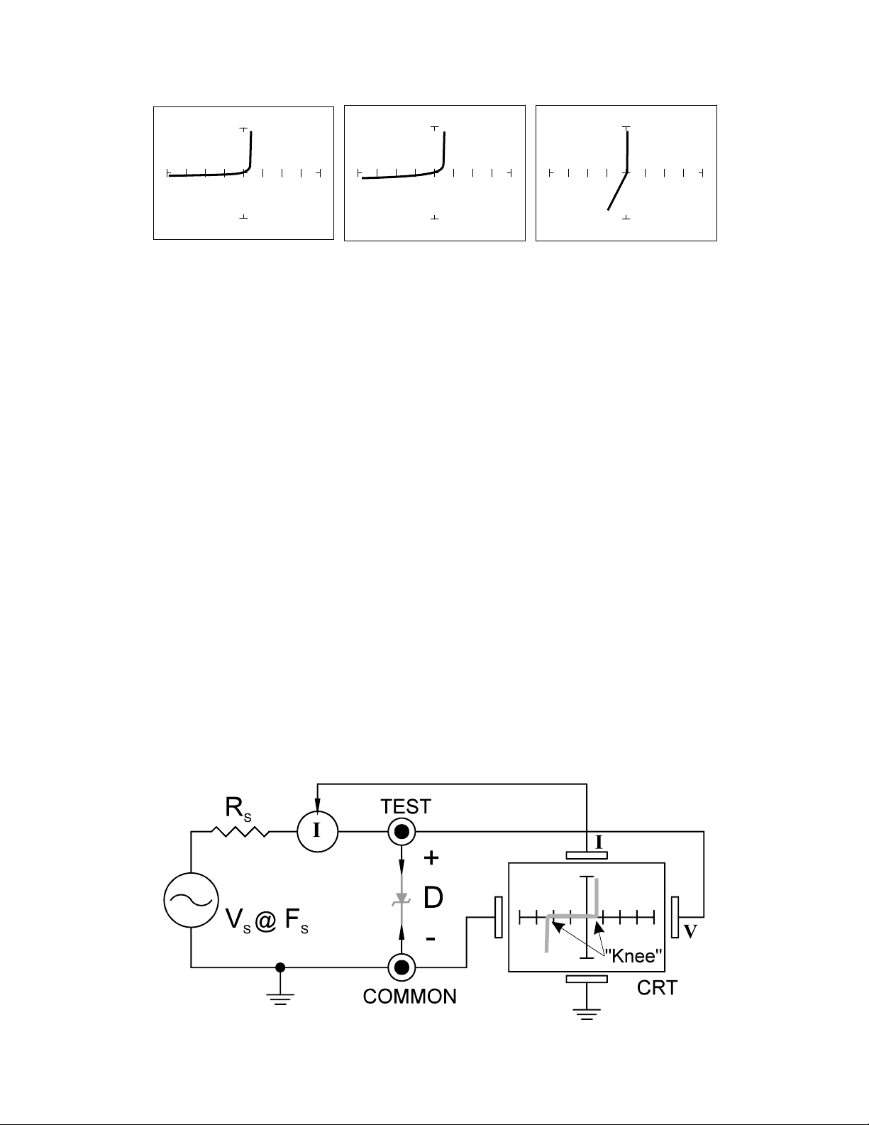
50 10V 1K 15V 50K, 20V
Figure 4-14. Signature of A 1N914Diode With Internal Leakage (10K In Parallel).
Notice that in the 50range, there does not seem to be a problem. In the 1Kand10K ranges, you
can see the diode conducting when it should be acting like an open. This is called leakage. The diode
acts like a diode when it is forward biased. When reverse biased, the diode acts like a resistor when it
should be acting as an open.
Zener Diodes
Normal switching and signal diodes conduct when forward biased only. When reverse biased, they act
as opens unless they are operated outside design limits. If this condition occurs then so much voltage is
applied that they break down and can no longer prevent current flow.
A zener diode is a different type of diode and is designed for operation when reverse biased (diode's
cathode connected to positive and anode to negative), but under carefully controlled conditions. When
the zener diode is forward biased (diode's cathode connected to negative and anode connected to
positive), they act as regular diodes and begin to conduct at approximately 0.6V.
When reverse biased, they act as an open until the applied voltage reaches their specified zener
voltage, at which time the zener diode begins to conduct current. Even if the reverse voltage is
increased, the voltage across the zener remains constant. It is this feature of zener diodes that allows
them to be used as voltage regulators and references. Because they conduct in both directions, the
zener diode's analog signature has two knees, one at 0.6V and the other at the zener voltage of the
diode. In ASA terminology, this two knee signature is known as the classic "chair" pattern that is
common in many solid state semiconductor components.