Tracker-2800-2800S.pdf - 第60页
60 Figure 4-9 . Composite M odel of a Diode and Resistor in Pa rallel. V S = 10 V, R S = 50 V S = 10 V, R S = 1K V S = 200 mV, R S = 1K Figure 4-10 . Composit e Signature - 1N914 Diode and 1K Resistor in Paral…
59
Composite Diode Signatures
A composite analog signature is a combination of several components connected together in an
electronic circuit. Up to this point, we have been showing you what the basic component signatures
look like out of circuit. In the real world of electronics troubleshooting, components are connected
together in a circuit and when testing with ASA, the signatures are a composite that may appear quite
complex. However, with knowledge of ASA fundamentals and experience you will find that even the
most complex looking signatures can be analyzed quickly and efficiently.
This section will introduce you to some examples of composite diode signatures.
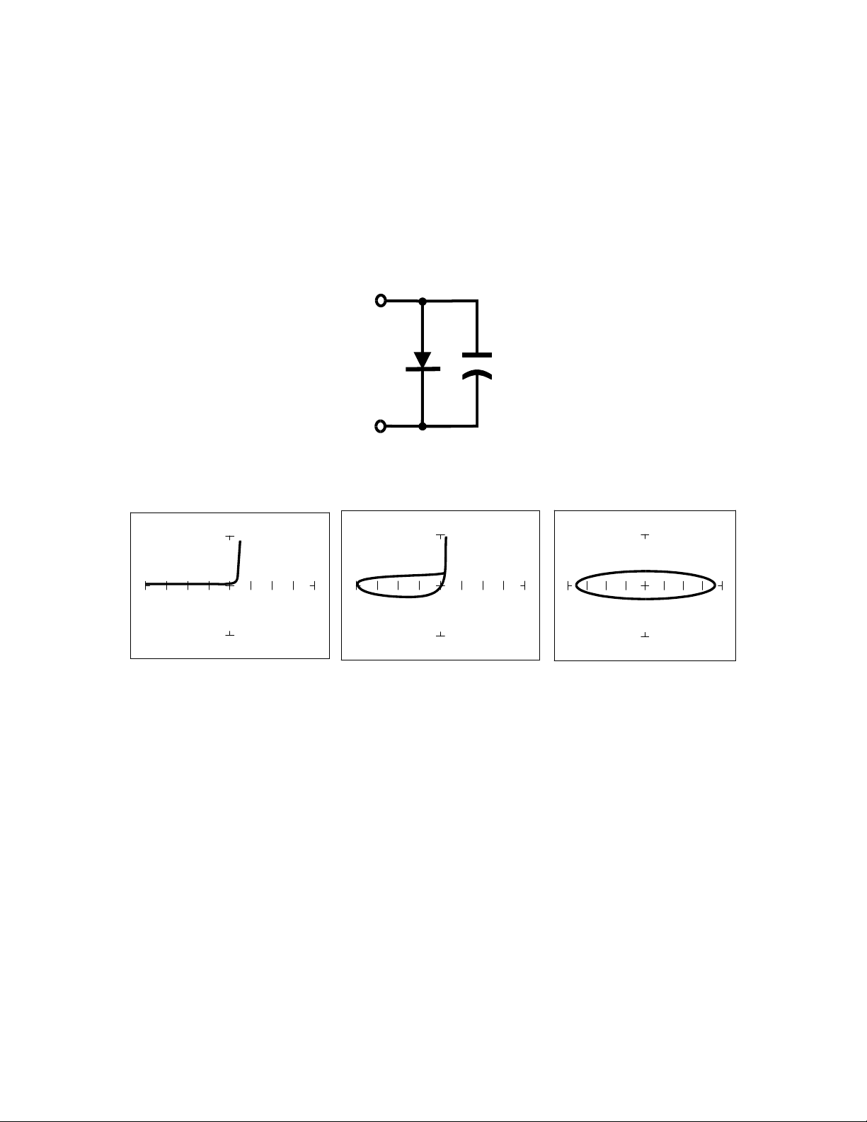
Figure 4-7. Composite Model of a Diode and Capacitor in Parallel.
V
S
= 10 V, F
S
= 20 Hz V
S
= 10 V, F
S
= 1KHz V
S
=200 mV, F
S
= 1KHz
Figure 4-8. Composite Signature - 1N914 Diode and 1F Capacitor in Parallel.
The signature on the left shows only the diode signature because the test signal frequency is set below
any visible contribution due the capacitive reactance. The composite signature in the center consists of
the distinctive loop of the capacitor and the "knee" pattern of the diode. The signature on the right
shows only the capacitor signature because the test signal voltage is below the diode's turn on level.
When multiple components are connected together, it's important to realize that the Tracker 2800 has
the ability to selectively display the signature of a single component.
60
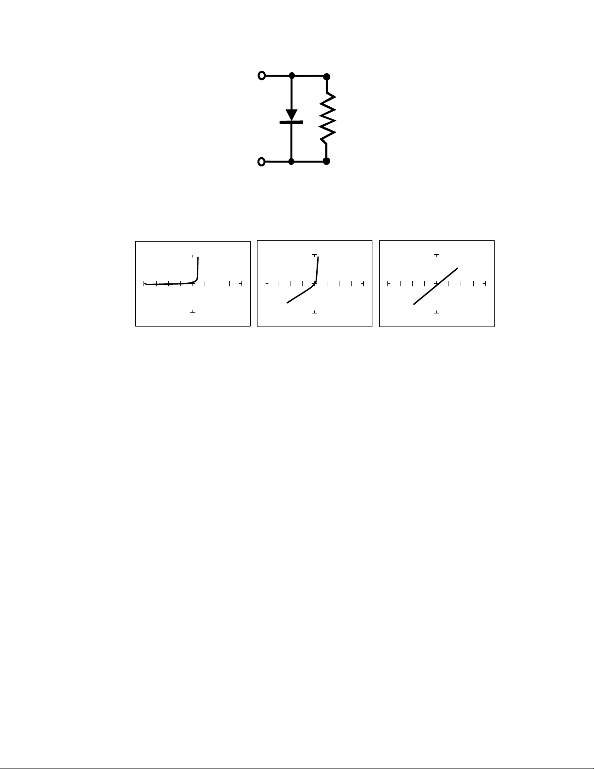
Figure 4-9. Composite Model of a Diode and Resistor in Parallel.
V
S
= 10 V, R
S
= 50 V
S
= 10 V, R
S
= 1K V
S
= 200 mV, R
S
= 1K
Figure 4-10. Composite Signature - 1N914 Diode and 1KResistor in Parallel.
The signature on the left shows only the diode signature because the test signal resistance is set below
any visible contribution due the 1k resistor. The composite signature in the center consists of the
distinctive slope of the resistor and the "knee" pattern of the diode. The signature on the right shows
only the resistor signature because the test signal voltage is below the diode's turn on level. Again,
when multiple components are connected together, it's important to realize that the Tracker 2800 has
the ability to selectively display the signature of a single component.
Diode Failures
Diodes can fail in a number of ways, and each type of failure will cause the signature to change. The
defective diodes often appear as open and short signatures. Two other types of flaws are internal
resistance and leakage.
61
Internal Resistance Fault in a Diode
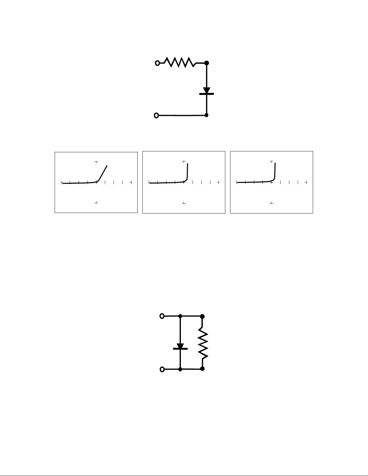
Figure 4-11. Defective Diode Model with a Small Series Resistor.
50 10V 1K 15V 20K, 20V
Figure 4-12. Defective Diode Signature with a 50 Series Resistor.
The 50 range shows that there is a resistive component to the signature when the diode is conducting.
This is the result of a defect in the diode's internal PN junction. The resistance is visible only in 50
range because the voltage drop across it is small. In the other two ranges, the resistance is masked due
to the internal resistances being too large to show such a small voltage drop.
Internal Leakage Fault in a Diode
Figure 4-13. Defective Diode Model with an Internal Leakage Resistance.